Another Super High End Phono Stage! No expense spared...

Try lm49729 or lm4562 or lme49990. They will surely bring smile on your face.Opa2134 is laid back like other Burr Brown opamps and youay be feeling little dull, slow sound.

Regards
Sachin

Cool, I already have one pair of 49990's on a DIP adaptor for another amp, so I'll pick up another.

About increasing gain. . .which resistor/s should be replaced with 100ohms?

Thanks again.
 
My CNC with variable gain PCBs turned out nice:

attachment.php


attachment.php


Edit:
A word about the variable gain.

Using 150R and 300R for the gain resistors, you can choose between 36, 40 and 44dB gain (at 1kHz). 40dB is the gain of the standard CNC circuit.

The resistor values can of course be changed. Change them to 120R and 220R, and the selectable gains will be 38, 42 and 46dB. Another example: 100R and 300R gives 36, 44 and 48dB.
 

Attachments

  • IMG_20141021_235138.jpg
    IMG_20141021_235138.jpg
    135.4 KB · Views: 452
  • IMG_20141021_235214.jpg
    IMG_20141021_235214.jpg
    137.4 KB · Views: 450
Last edited:
Hello, and welcome to AudioKarma!

Yes, there are several posts with parameters of boards. Use the search function in this thread and you can find them easily.

If you are specifically asking about the PCB that skrodahl just posted about, ask for measurements of his board, or you can send him a PM.
 
Last edited:
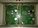
The dimensions of the board that I had made are 4x3 inches, but I suspect that you are asking for gain, THD/noise, frequency response, RIAA response, THD etc.

I have not done any serious measurements, but the praise shown for the CNC in this thread gives a clue about real life performance. The gain is easily calculated (at 1kHz), and is shown in my previous post. The frequency response depends on the opamps, and the RIAA curve is very decent thanks to a tried and true passive RIAA filter.

Rod Elliot's P06 RIAA stage uses an active low frequency filter and a passive high frequency filter. It is otherwise quite similar, being a two gain-stage opamp circuit. He is providing some performance numbers in his article.

Apart from that, it all depends on the components you choose, the input impedance/capacitance, enclosure/shielding, interconnects, pickup, turntable etc.
 
CNC phono

Hi, every body of this groups,
I jointed Ak for very long time ago, but i had several posts only.
Some weeks ago, i had the board from local audiophile. I found that is the same cnc phono board what you have been discussing.
IMO this is wonderful phono stage i have heard vs with many phono stage i have. Therefore base on this one, I would like to upgrade to MC phono by add more opam... because of I had several MC carts.
Could you please support me by the circuit?
Sorry i don't known how to post a picture.
Many thanks and regards
 
How one can measure CNC for performance? I have oscilloscope with FFT function and 50MHz signal generator with capability mV to 10V. Only 1KHz sine wave at few mV amplitude at input is okay for FFT analysis for THD?


Sent from my iPad using Tapatalk
 
How about a smaller PCB, and variable gain?

attachment.php


Two layers for reduced interference:
  • Bottom: Audio path + ground fill
  • Top: Power, anything outside of audio path + ground fill

attachment.php


attachment.php


In addition:
  • Much shorter tracks
  • An extra GND pad for turntable ground at input
  • Power input pads much closer together, and away from audio out
  • Audio in and out pads positioned so that three-lead shielded cable can be used

Size is 97x53mm (3.8x2.0"), Eagle files attached. When opening the board view in Eagle, click Ratsnest to create the ground fill.
 

Attachments

  • cnc-dual.jpg
    cnc-dual.jpg
    123.5 KB · Views: 240
  • cnc-top.jpg
    cnc-top.jpg
    119.6 KB · Views: 236
  • cnc-bottom.jpg
    cnc-bottom.jpg
    121.6 KB · Views: 239
  • CNC-dual.zip
    87.7 KB · Views: 25
Last edited:
Looking good! It would work, but I think it's time to think better grounding scheme now. Now I am inspired from Pass Pearl-2 phono PCB. [emoji39]
It implements star ground where all ground current run towards central connection of PS filter caps.

Sent from my iPad using Tapatalk
 
Looking good! It would work, but I think it's time to think better grounding scheme now. Now I am inspired from Pass Pearl-2 phono PCB. [emoji39]
It implements star ground where all ground current run towards central connection of PS filter caps.

Sent from my iPad using Tapatalk

Thanks omishra,

I may very well be absolutely wrong on this, but...
It doesn't seem to me that removing copper from the ground fill will improve anything. The ground will remain grounded anyway, it wouldn't run anywhere.

Isn't it better, from a shielding point of view, to keep the liberal amount of ground on the top and bottom layer?

This is all guesswork from me, I'm open for suggestions. The Eagle files are there to be edited and improved as well.

If there's any interest, it would be very easy to turn it into a single layer as well. The power input would end up between the right and left audio output, but there will be no other side effects on the layout.
 
Please don't take my comment as criticism. You have already made nice artwork. But was mentioning what I learned from my experience while designing PCB for that pearl-2 phono. Initially I made PCB for this too. But you must agree, improvement is always thought of.
Btw this PCB will work as it should be.


Sent from my iPad using Tapatalk
 
I assure you, I am not taking it as criticism at all. I am just eager to learn from your experience. Could you show me what you did for the perl-2, so I can see what you mean?
 
Okay, see this! Please follow link.

Here you will find thick track between R13 & R26, left side of blue preset. That is centre point where power supply ground references are coming from + and - sides are connected, see unused golden solder pad. For input circuit all ground lines from input, load setting resistance and grounds from RIAA passive components are connected separately to this central ground sink without any cross talk of ground currents. This may be minute current but for mV levels it makes low noise floor, enhances accuracy.

Btw I will try to make one similar for CNC too, will take some time , may be 2-3 days.


Sent from my iPad using Tapatalk
 
Last edited:
Btw I will try to make one similar for CNC too, will take some time , may be 2-3 days.

Thanks for the explanation. So what you're saying is that there might be variations in the ground potential with such a huge ground area? Would an extra ground pad, one that connects to a central star ground within the chassis, make any difference? ...or am I missing the point?

It will be really interesting to see, because I still have problems picturing it. A picture of the bottom side of the PCB would perhaps clarify things a bit better.

A single layer version of my previous Eagle design might interest those who etch their own boards. No difference, except that the signal output and PSU input has to be routed in another way. Same board size with variable gain:

attachment.php


I also made the traces a bit wider, which helps when etching at home. Very little copper needs removing, so it should be much easier to etch.

Eagle files are attached. Again, in board view, click the Ratsnest button to create the ground fill.
 

Attachments

  • cnc-vargain-single.png
    cnc-vargain-single.png
    109.4 KB · Views: 202
  • CNC-single.zip
    148 bytes · Views: 25
hey i have had the CNC board for a while and just now getting to the project. Digikey is out of all the panasonic metal film resistors and the 1uF 50v low noise stacked metal film cap. anyone in the states have extra of these i could buy? i ordered all the remaining parts they had in stock.

in addition to the 1uF 50V cap the 1/4w 1% panasonic resistors needed are:

-8.2 kohm x1
-100 ohm x4
-150 ohm x4
-18 kohm x2
-2.2 kohm x2
-200 ohm x2
-27 kohm x2
-33 kohm x2
-47 kohm x2
-62 kohn x2
-750 ohm x2

thanks in advance! looking forward to a battery powered phono stage as a Xmas gift to myself
 
Back
Top Bottom