KR-9600 restoration ..yet another

KenMood

piece of work
Hello,

Recently I acquired a KR-9600 which I was planning to restore.

After determining the overall condition of the receiver and the TA-200W modules (both turned out fine with help of the info found on this forum)

EW has helped me here pointing me in the right direction with an input problem, which turned out to be a transistor I installed backwards on one of the amp boards. (in the Netherlands we call that 'onnozel'.... fill in the blanks here)

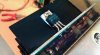
Attached are some before pics. This unit was pretty invested with that good ol'brown dust blanket. It looked like a whole new ecosystem. I cleaned it out roughly and removed the main filter caps as the old ones were leaking badly, they were actually dripping and it was sticky all over the place, even traceable all the way back to the car.

I ordered parts from Digikey and started my way through the unit using all the info I could find here.

Work I am planning to do:
- thorough cleaning
- deoxit / clean all controls, connections and switches
- all new fuses
- rebuild the amp boards with all new components, getting DC offset to an acceptable value
- clean the heat sinks and use new compound
- recap the boards, check all solder joints
- Tuner opamp mod
- preventive actions to power supply / add 25W resistor
- new bulbs
- triple check all the work
- Power switch mod (@230V AC) - thanks Hopjohn
- ?

I will post the progress made in the days ahead.
 

Attachments

  • AK_9600_001.jpg
    AK_9600_001.jpg
    99.9 KB · Views: 167
  • AK_9600_002.jpg
    AK_9600_002.jpg
    233.1 KB · Views: 146
  • AK_9600_003.jpg
    AK_9600_003.jpg
    207.1 KB · Views: 148
  • AK_9600_004.jpg
    AK_9600_004.jpg
    117.2 KB · Views: 143
  • AK_9600_005.jpg
    AK_9600_005.jpg
    193.9 KB · Views: 180
Last edited:
Progress on removal of filter caps, amp boards and heat sinks.
 

Attachments

  • AK_9600_007.jpg
    AK_9600_007.jpg
    86.1 KB · Views: 123
  • AK_9600_006.jpg
    AK_9600_006.jpg
    96.5 KB · Views: 141
  • AK_9600_008.jpg
    AK_9600_008.jpg
    77.8 KB · Views: 125
Here's an update:

a lot of progress has been made thus far. So far I've spent a good 20 hours.

The filter caps have been replaced and mounting completed. I used the 383LX123M100N082 from CDE. These are 12000uF/100V 105°C

Cleaned all of the board with the diode bridges and installed new fuses.

After testing of the modules earlier and solving the aforementioned input problem the amp boards have been cleaned and rebuilt. I used matched 2sc2240BL / KSC3503 / KSA1381, I had a bunch of new 0.5W resistors which fitted and used new diodes, jumpers. Au revoir'ed the Ce2 and Ce13 input tantalums and installed the Panasonic ECW-F2155JA. Info about this mod I found here

The amps have been put back into place and the wiring has been neatly restored. One of the perks of being a sysadmin / hardware engineer is the access to different kinds of high quality heat sink compound :nerd: so I know this should be more than good. I created an evenly distributed layer of compound with a plastic straw from a discarded compressed air spray can. Too much compound will lead to a squeezed hamburger effect and it's a mess to clean up. Use q-tips with IPA.

After the now mandatory triple check the unit was tested with DBT and all was fine. Without DBT the offset reads about 9mV for left and right 5.2 mV. I will leave that alone for now. With the amp jumpers removed, an mp3 player yielded great detailed sound and punchy bass.

In the next posts the recap of the power supply board /tuner and further cleaning will be dealt with.

The attached pictures are a mix of mobile phone and dslr so quality bounces up and down a bit:)
 

Attachments

  • AK_9600_013.jpg
    AK_9600_013.jpg
    218.5 KB · Views: 120
  • AK_9600_012.jpg
    AK_9600_012.jpg
    76.8 KB · Views: 98
  • AK_9600_011.jpg
    AK_9600_011.jpg
    76 KB · Views: 108
  • AK_9600_010.jpg
    AK_9600_010.jpg
    90.5 KB · Views: 122
  • AK_9600_009.jpg
    AK_9600_009.jpg
    229.8 KB · Views: 123
  • AK_9600_015.jpg
    AK_9600_015.jpg
    113.5 KB · Views: 132
Last edited:
Post #25 is the Triac ..

You mean the heat issue mentioned there?

I have yet to decide what to do. I already noticed this switch is arcing so a good clean and rotate of those spoons should at least be done.

Any opinions on this? if heat is becoming a concern maybe a relay is the best option.
 
Last edited:
- replaced the old C1419 toaster element with a new OnSemi MJE15032G
- new relays
- recapped power supply and made a start with tuner recap
- made preparations for the new tuner opamp with a new IC socket


waiting for parts now, MJE15033G, 25W resistor, .22 caps for opamp, stacked polys.
 

Attachments

  • AK_9600_017.jpg
    AK_9600_017.jpg
    85.4 KB · Views: 118
  • AK_9600_018.jpg
    AK_9600_018.jpg
    213 KB · Views: 106
  • AK_9600_019.jpg
    AK_9600_019.jpg
    241.6 KB · Views: 102
  • AK_9600_020.jpg
    AK_9600_020.jpg
    75 KB · Views: 99
  • AK_9600_021.jpg
    AK_9600_021.jpg
    176.6 KB · Views: 106
  • AK_9600_016.jpg
    AK_9600_016.jpg
    117 KB · Views: 106
Last edited:
Since I'm waiting for parts I started cleaning the pots and connector pins on the switch / preamp board. There had been some intermittent connection issues. I could not find the Brasso in the garage (somebody probably borrowed it and not returned same as some tools you never see back again) so I used some DeOxit on a q tip. I cleaned all the pins thoroughly.

Just as I slid back the female connector I noticed they had too much play. I could spray DeOXit in there but just like most automotive connectors you can use a small pin (a cut off lead from a cap) to unhook these. The tiny hole next to the bigger one is the trick (see pictures). Once unhooked I bent the female sliders back together carefully and bent outwards the small clip that locks it in place and now they fit snugly on the connector pins again!

Don't want to sound like the bad Sherlock but I could not find any info about it here :thmbsp:
 

Attachments

  • AK_9600_022.jpg
    AK_9600_022.jpg
    79.7 KB · Views: 115
  • AK_9600_023.jpg
    AK_9600_023.jpg
    84.1 KB · Views: 114
In my previous employment I actually had a tool that fit down the large hole and small one at the same time. Had a plunger on it...depress the plunger and the pin pops out.

Looks like your method works just as well.
 
Today I found a couple of about-to-be-thrown-away processor VRMs from an ancient Compaq server. I popped off the heat sinks because I had a plan with them:

Their dimensions are perfect for the stock power supply heat sinks. I drilled a 2.5mm hole exactly in the middle and added a longer screw. Now with some new compound they are a nice addition for some extra cooling.

The 25W resistor is ordered so once installed this should prolong the life of this board which gets really hot after a while.
 

Attachments

  • AK_9600_024.jpg
    AK_9600_024.jpg
    192 KB · Views: 130
This...

The 25W resistor is ordered so once installed this should prolong the life of this board which gets really hot after a while.

..is going to make everything considerably cooler. If browning of the board is an accurate indication of some stupid bad heat (previous experiences) then the two resistors in series on the north side of your photo are the primary offenders.
 
That's right, especially those 2. I wonder what the engineers were thinking back then. I'm not a rocket scientist but those are an obvious and absolute design flaw.
 
After a short vacation I could collect the parts at my local shop.

I have installed the 25W resistor thus far, I removed the old resistors and created a new wire wrap and put on fresh compound on the newly installed OnSemi.

next up are the stacked polys and finishing of opamp.
 

Attachments

  • AK_9600_025.jpg
    AK_9600_025.jpg
    237.8 KB · Views: 116
Last edited:
You are obviously a very talented individual to be able to tackle this restore job. I had a KR-9600 in 1977 and I traded it to a college buddy for his Marantz 2275B - what was I thinking? I was too snookered at the time. What does a fully restore KR-9600 bring these days?
 
Thanks, I have restored a number of Kenwood receivers and amps and still learning new stuff every day but the real deal of talent is found in the dedicated people here that brought up all the mods and tips on how to test and diagnose the KR-9600. I collected all of this information in order to perform a decent restore. It requires a lot of patience, a DBT, Pink Floyd playing in the background and some courage I guess.. :music:

For sure this is not a real beginner's receiver. In retrospect, the sheer size of it alone can scare the crap out of you but I can't emphasize enough that if it weren't for this forum I would have never tackled it.

I don't know what a fully restored KR-9600 is worth, I live in Europe and the prices are a lot higher compared to the US. On Hifishark I even see mint condition asking prices in excess of 1250 Euros! Seems insane? They start to become rare and that's what sellers use as an argument for sure but trying to find a working unit for around USD $250-400 should be manageable.

For kicks, maybe you can ask the college buddy to trade again:D

cheers,
Peter
 
FM opamp voltage tweaking

This weekend I got the Fairchild diodes and tried the next setup:

OpAmp: Analog Devices AD823
2x .22uF stacked polys to ground

Dk4: 1N5242B 12V 1/2W
(Dk2: 1N5244B 14V 1/2W)

I checked everything and measured the supply voltages to be +12.48V and -12.57V which should be okay I guess.

The offset is a bit weird but IMHO within comfort: on the right I measured 0.1 or 0 mV DC and on the left there's 7.5 mV DC (measured on the pins labeled 29 (R) and 32 (L) and GND pin 30.

I had already jumpered Cb47 and Cb51.

The sound of the tuner is much cleaner now, voices and instruments sound clear and much more detailed. I listened to various stations, really loving the stereo image of this tuner. Kinda got stuck in a quiet piece on the classic station, especially cellos and brass instruments are excellent. Even coughing and sneezing in the audience sounded more moisty:D

Should I consider this a 'job done' or can I tweak something to get the DC offset voltages more balanced? Or is it just a characteristic from within the IC?

thanks!
Peter

and yes I was a bit thirsty.
 

Attachments

  • AK_9600_026.jpg
    AK_9600_026.jpg
    141.5 KB · Views: 65
Last edited:
The only thing that's going to change the offset is a different opamp. I like to see the offset under 5mV, but if you're not hearing any pops or clicks when flipping the dials and switches when set to FM, then you're good to go.
 
Back
Top Bottom