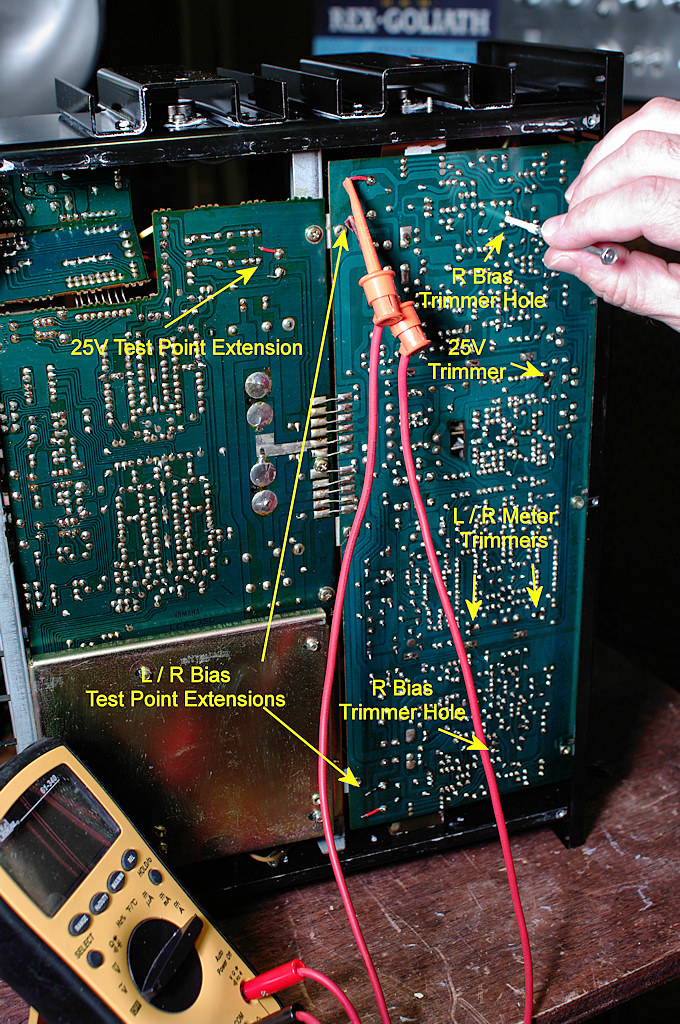
Here's the photo with test locations and the extensions shown. I made one extension per pair longer than the other so the grippers could hang without bumping too much. I stripped about half the length of each wire's insulation off to make a loop to crimp around the resistor leads (with the resistor desoldered this works well). If you'd rather just make the loop and press it on while heating up the solder that's already there, remove all the insulation and grip the bare wire with needle nose pliers. After it's in place, thread the insulation back onto the bare wire. As to shorts, by only removing about half the insulation, there's only about 1/16" - 1/8" exposed at the end for the clips to hook onto. After everything's set, I slide the insulation back over the end, leaving the now-exposed portion of the extension right next to where it's soldered. Sticks up no further than any of the other leads on the board. If it still concerns you, you can always put a piece of electrical tape on the board under the wires, and then another on top of them after you're finished with setting them.
You could also get "fancy" and make a little bend in the wire away from the board right next to the solder connection, and then have it bend back flush with the board (which I may still do). That way the grippers will have a little "hook" to clamp on vs possibly slipping off the end of the wire (ask me why I've thought of this).

EDIT: As I've yet to purchase dummy loads, nor made up a 1kHz test tone, I don't intend to fool with the meter trimmers unless absolutely necessary. I did, however, solder 1/8" female terminals on the ends of the disconnected meter wires for easier removal of the front panel if needed in the future. This way, no need to solder them back in place.