SX-1980 power supply problems

txturbo

AK Subscriber
Subscriber
My first Pioneer...

I picked up a decent looking SX-1980 that had some obvious problems from the bay. As I proceeded to investigate it looks like someone has been in this beast before me. :thumbsdn:

Powered it up on the variac, tuner acts strange and no output.

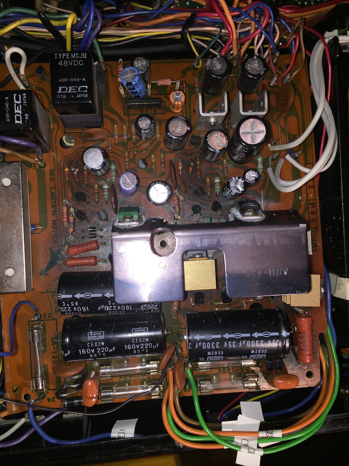
Checked the power supply voltages and found the +80V running high at 92 volts and climbing.

The PS board looks like crap and is just floating around, all of the plastic mounts are broken.

I flipped it over to see some of the previous handiwork.

19425705586_290e4ae026_h.jpg


19456056641_776b052960_b.jpg


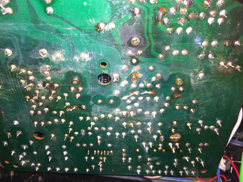
This reminds me of a sign that I once saw in a TV repair shop:

"Hourly rate is $75 per hour.. $150 if you tried to fix it first"

I guess I should just pull the board out and rebuild it or should I try and service it in place? The board actually looks a bit warped.
 
Rebuild it completely. Check all resistors for value, ceramics should be fine.
Removing it will not make the job any easier. The PS is the most time consuming board to manage. Double check your work. One backwards transistor will make you start over from scratch. :yes:

You will need to build EW's CCS component(s).
Theres a lot on this set: Matts Thread

It is a Masterpiece! Congrats!!!!
Take your time and good luck!
 
Last edited:
Rebuild it completely. Check all resistors for value, ceramics should be fine.
Removing it will not make the job any easier. The PS is the most time consuming board to manage. Double check your work. One backwards transistor will make you start over from scratch. :yes:

You will need to build EW's CCS component(s).
Theres a lot on this set: Matts Thread

It is a Masterpiece! Congrats!!!!
Take your time and good luck!

I'll take it easy on this beast! Actually I can hardly flip it over without breaking my back.
 
Tip for working on it:

Stand the unit on it's side, desolder the wired pins by the fuses, allowing the board to swing out perpendicular to the chassis, then a TOTAL rebuild. NO HALF MEASURES. It is VERY unforgiving of mistakes.
 
Has anyone ever made an entirely new board for this?

Since almost every part on the board will be replaced maybe it's a good idea to just make a new PCB with all of the changes built into it.

If you could make a new PCB what changes besides the current source and remote regulator would you make? I really don't care for the wire wrap terminals, a real connector set would be much better IMHO...

It's just an idea.... :scratch2:
 
Entirely new board? No.

New e-caps, transistors, diodes and a few low resistance resistors doesn't translate out to all new parts, in fact you will play he## trying to find r220 to r223 (precision f/b divider) with appropriate wattages AND tolerances - I TRIED...


edit THIS time they showed up. so I am listing them here until I can get them into my spreadsheet, my other ("server") system is down due to a power failure..

SX-1980 awr-054 r220 59k ohms 1/2 watt 1% metal film yeago 603-MFR50SFTE52-59K
SX-1980 awr-054 r221 51k ohms 1/2 watt 1% metal film yeago 603-MFR50SFTE52-51K
SX-1980 awr-054 r222 59k ohms 1/2 watt 1% metal film yeago 603-MFR50SFTE52-59K
SX-1980 awr-054 r223 51k ohms 1/2 watt 1% metal film yeago 603-MFR50SFTE52-51K
 
Last edited:
R213 is the old q207 cc source circuit's zener protector circuit.

lol, yes a bit toasty. don't think it's 100 ohms anymore...

Looks like the factory dual zener (for the 35v reference) was installed, as well as a couple of new caps.

Some new power rectifiers (d201, d202, d205 and d206) and the orange, green and brown wires from the transformer were unwrapped and resoldered... :yuck:
 
Last edited:
Entirely new board? No.

New e-caps, transistors, diodes and a few low resistance resistors doesn't translate out to all new parts, in fact you will play he## trying to find r220 to r223 (precision f/b divider) with appropriate wattages AND tolerances - I TRIED...

Is the tolerance better than 1%? I think mouser has the 59k and 51k 1% 1/2w.


r213 is looking a bit toasted ...

R213 is the old q207 cc source circuit's zener protector circuit.

lol, yes a bit toasty. don't think it's 100 ohms anymore...

Looks like the factory dual zener (for the 35v reference) was installed, as well as a couple of new caps.

Some new power rectifiers (d201, d202, d205 and d206) and the orange, green and brown wires from the transformer were unwrapped and resoldered... :yuck:

The board looks like a Pop-tart I really want to try making a new board.. Maybe I am over thinking it :D
 
Whatever floats your boat, either keep the original board for later on, OR rather than trashing it, I'll be interested in having it.

I have delt with FAR worse messes. Successfully.
 
I got the parts from Mouser yesterday to start the rework on the board... This board really sucks! I noticed that the pad for the +80 regulator was gone and the crispy resistor was not completely soldered in. So I fixed that and gave it a quick try... No bueno..

I could take the board to work and have it duplicated, with any mods needed. If I did would there be a potential market for it? I really don't want to get into the board business however if it solves the potentially largest problem with this receiver and there is a sufficient number of receivers that need the board maybe it's worth it? I suspect that in small volume it would probably cost ~$200 to make it. To make a single board for my own use would be a bit crazy.

It would have the current source mod and connectors for remote mounting the regulators. It could also have all of the component ID's silkscreened on the board with the test voltages. I would also make the holes for the wire posts a tiny bit bigger for ease of installation.

The only part that I see that may be a problem to source is the protection IC. I guess it could be moved over but that kind of defeats the purpose of a new board.

Comments???
 
It is a lot of work for a very small list of customers. So as a business, it is not very profitable, as the return on investment is low.
You could either just re-use the old protection IC or do away with it and re-design using discrete components as is done with SXx50 designs. Board space maybe an issue but you may save space if you do a double sided pcb and possible smt to save some space.
 
You have to go full replacement with components on that PS. No half a$$ attempt. The other components are stressed out and will fail on power up. I learned this the hard way. MTF was telling me this several times "Deal your self a new deck"! You will chase your tail and get frustrated. All new components, double check your work many times over before you fire it up on the DBT. You can risk damaging the FM tuners HAL chip by not following through with the seasoned advice.
Soap box is now put away. :D

I plan on replacing all the caps, silicon, most of the resistors and relays.
 
I plan on replacing all the caps, silicon, most of the resistors and relays.

You had better research your parts carefully, from the special BOM type information provided in the SX-1980 service manual AS DECODED BY the tuning fork publications (sticky near top of forum list).

edit 2022
Little did I know...
TxTurbo is a stone PRO.
He has a viewpoint and resources out of reach of mere mortals. It helps when you own a company that resurrects and rehabilitates prior generations of high tech industrial equipment.
 
Last edited:
When I dropped off my 1980 two months ago at Matts, we discussed then about the extent of rehab. I told him to make it right and correct. Crazy to go less....especially after hearing his unit.
Anxiously awaiting word to when he will start looking into it.

Sent from my LG-H345 using Tapatalk
 
I have decided to make a new PCB..

I marked all of the wires and pulled the board last night. The board is in the trusty hands of our board specialist at work. He already has the schematic nearly completed and will start the layout of the board.

The design will basically remain the same as the original, with all of the components and traces. The only exceptions will be the current source mod and connectors to remotely mount the regulators. All of the components will be identified on the face with the silkscreen as well.

It would be great if every component were new.. This would allow boards to be made that are drop in replacements without transferring any components. I will look at the protection scheme from the SX-XX50 and see if it's reasonable to make it all out of discrete components.

I really don't like the wire wrap connections. It would be really easy to add connectors to the board. I know this detracts from the originality but makes service very easy. Many of the wire wrap connections have already been soldered or the wires are loose. There are some nice connectors with screw down connections rated at something like 10A that would be easy to install. Comments?

I'll post the schematic, layout and bom before making anything. I would appreciate any comments or suggestions.

We have some DC power supply test equipment at work that basically sits unused. I will probably rig up a test fixture to make sure the board works before I try and install it.
 
Back
Top Bottom