AU-G99X Amp Intermittent Input Loss

DonQuixote99

just give me some truth
Just picked up this at a Goodwill at, well, a fancy price for Goodwill, but it seemed like a real good deal for a powerful Sansui integrated amp. Before purchasing I checked it out in the store and both channels seemed to work fine.

Took it home, hooked it up, and whoops--left channel is gone. Verified speaker connections, they seemed OK. Switched the input jacks, and same channel stayed out. Moved input from CD to Aux, and left channel still out.

Noted that in addition to no sound, left channel led display showed no activity. Right channel leds show activity whether speakers are on or not, varying with volume setting.

So I took it to the bench and opened it up. Fuses look ok. Took one out and tested it, other not yet, too hard to get at. Powered it up and carefully evaluated different control functions (with CD input coming in). Heard no noise, and no effect on left channel. So, I thought, it worked at the store, it doesn't work now, that has to be a connection that connects only sometimes. Almost at random, I rapped a little on the shield by the input section.

The left channel came on!

That strongly implies the connection problem is with the input assembly under that shield. At this point, suggestions on how to fault isolate further and fix will be appreciated.

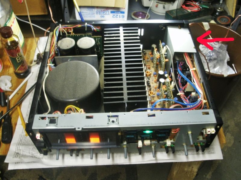
Pic 1) shows chassis with top off, both channels working (note leds). Red arrow points to shield at right rear that I tapped-on.

AU-G99Xinteriorresized_zps0a17b517.jpg


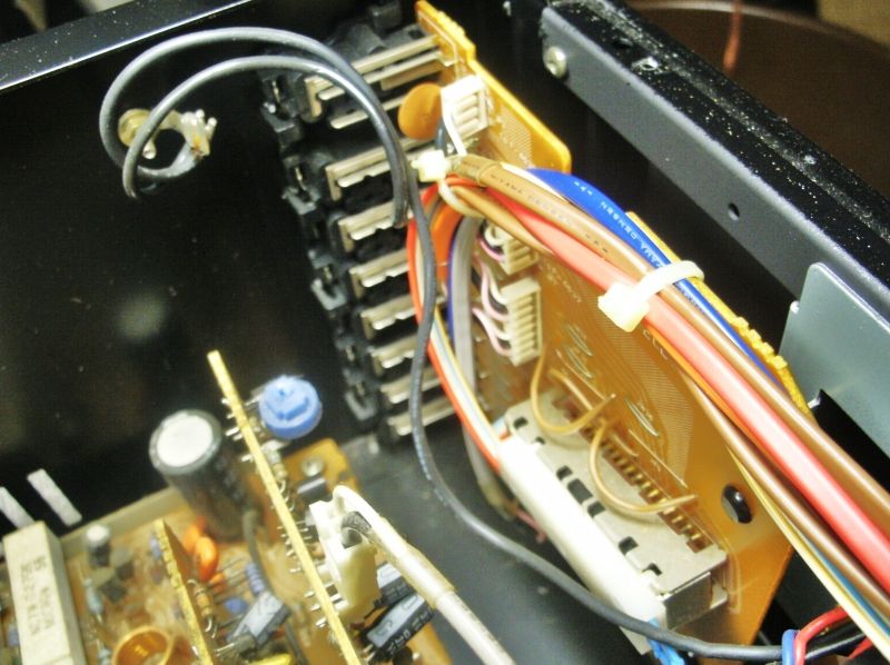
Pic 2) shows input board after shield removed. Don't think slider switch is involved--that selects input for rec function.

AU-G99Xinputboardresized_zpsf5e176a8.jpg
 
Speaker relay ?

If you push up the volume , do the left channel come back sudently in a bang ?
 
Speaker relay ?

If you push up the volume , do the left channel come back sudently in a bang ?

He says the power meter stops on the channel that cuts out when he taps the right side rear - and the speaker relays are on the left side rear, behind the filter capacitors.
 
Speaker relay ?

If you push up the volume , do the left channel come back sudently in a bang ?

Never did. Only the tapping had effect. Came back suddenly, not with a bang fortunately (didn't have it cranked up much).
 
Last edited:
My guess is a cracked solder joint on one or more of the input sockets - or a cracked PCB - the input sockets are pretty vulnerable to knocks from the rear as they are soldered to the PCB.
 
My guess is a cracked solder joint on one or more of the input sockets - or a cracked PCB - the input sockets are pretty vulnerable to knocks from the rear as they are soldered to the PCB.

It's more than one--or a connection that's common to more than one left input.

I suppose the idea is to pull the input board and ... well, and do what exactly?
 
CLOSELY examine all the connections from the input sockets to the PCB - and a VERY CLOSE look at the PCB for cracks - you may have lost a 'ground' which would explain the multiple inputs loss...

As I said this design of amplifier is very vulnerable to impacts from the rear - to the input sockets and to the speaker posts (especially).
 
if its all inputs .
things common with one channel are ....rca lead .... input selector switch .... cable from input board to pre-amplifier . a copper trace on the board or solder joint
 
if its all inputs .
things common with one channel are ....rca lead .... input selector switch .... cable from input board to pre-amplifier . a copper trace on the board or solder joint

To go through your list (consulting service manual):

1. rca lead: no. When input leads are switched, problem stays with left channel.

2. input selector switch: no. Selection is done by push-button on a board on the front panel. There are four multi-conductor leads going from the input panel in back to that board.

3. cable from input board to pre-amp.: no. that connection goes from front panel selector board, would not be affected by torque on rear input board.

4. a copper trace on board or solder joint: possible

The other possibility is the connectors & leads going from the input board to the selector board.

I've done a little more 'testing.' When I tried it again, the left channel was out again. I tapped on top edge of rear input board: no effect. Carefully tried a number of ways to tap-on-things or push-on-things. Left channel came on when I pressed on the JP 6 connector (circled in red on pic).

AU-G99XinputboardJP6circled_zps97a68534.jpg


Are those pin connectors, and removable? If appropriate, I'll try removing it, applying deoxit, and reseating it.

And I realize that the bad connection could be somewhere else, and not be JP6 at all....
 
could be a bad solder joint on the board or a cracked trace then .
and yes it could be a bad connection on the plug pins or wire connections .
what is the switch for on the board then ? is that the record switch ?
 
could be a bad solder joint on the board or a cracked trace then .
and yes it could be a bad connection on the plug pins or wire connections .
what is the switch for on the board then ? is that the record switch ?

Yes, record switch.

I'm hoping the problem is that jumper connector, and I'm hoping that if i pull and reseat it, all will be well, without having to pull the whole board (that disassembly seems a bit tricky.) But this idea depends first on that jumper connector being removable, a pin and socket sort of thing. I've seen some like that, and some that have to be unsoldered to be removed.

Anyone happen to know which kind that is?
 
Try connecting a source to the tuner input, that goes through the three pin directly above the connector you are having problems with. See if you get both channels.

Cheers

John
 
Try connecting a source to the tuner input, that goes through the three pin directly above the connector you are having problems with. See if you get both channels.

Cheers

John

Have done it. Left is missing there too, when it's missing.
 
I have the similar problem on my G99X. Except on mine only the phono occasionally starts fading and cuts out on the right channel. A gentle tap on the side by the phono selector knobs fixes it. All other inputs work fine and sound is great!
 
Yes, record switch.

I'm hoping the problem is that jumper connector, and I'm hoping that if i pull and reseat it, all will be well, without having to pull the whole board (that disassembly seems a bit tricky.) But this idea depends first on that jumper connector being removable, a pin and socket sort of thing. I've seen some like that, and some that have to be unsoldered to be removed.

Anyone happen to know which kind that is?

The (wired) plug just pulls off the PCB header - you should not need to remove the header to clean the pins.
 
Found that at GW? Damn. Great find. Mine's on Mattsd's bench right now. Full resto.

Once you get it up and going, you're gonna be spoiled. Absolutely brutal power and sweet sounding amp. Had mine since 1989.

Good luck.
 
The (wired) plug just pulls off the PCB header - you should not need to remove the header to clean the pins.

Do you mean that each wire comes out of the white thing, or that the white thing with all the wires in it comes away from the board? Tried a little to make the latter happen, and it did not show any sign of happening. Am afraid to try too much....
 
Have gotten the board out of its position in the chasis (with all wires still attached. Have looked it over carefully and don't see any cracks, broken solder joints, or damage. Tested all leads and traces on the back for continunity; all seem good at this time. Tested the ground connector coming from each set of RCA sockets (before it gets to the board for continunity to chassis, all were good when tested.

I am thinking that we have all the inputs on the left bad--intermittently, but all at once when they are bad. The only thing all these channels have in common is the ground side of the circuit. So we are looking for a point where the ground return can be interrupted and take out all these inputs at once.

So I'm looking at diagrams and pondering this. More later....
 
Last edited:
Do you mean that each wire comes out of the white thing, or that the white thing with all the wires in it comes away from the board? Tried a little to make the latter happen, and it did not show any sign of happening. Am afraid to try too much....

All of them together, but it will be 'keyed' so might be a little reluctant to come off - take a CLOSE look at it - you should be able to see how this works and therefore not apply too much force.

If you are that reticent about it, then I suggest you leave it to a tech, it should be a relatively simple fix - but so easy to make a real hash of it.
 
Last edited:
Back
Top Bottom