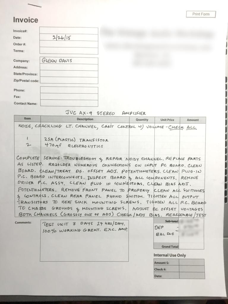
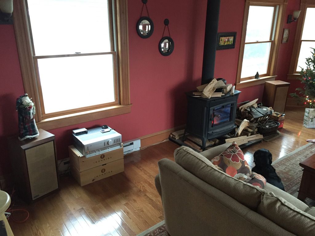
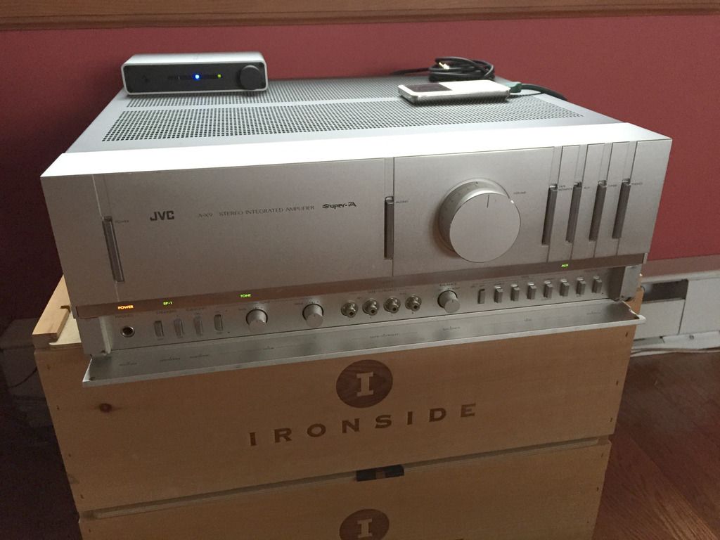
So here's the repairs needed, quoted from Tom's ongoing updates to me. It's long and you can see this amp is quite complex.
"Quite a bit of work done on the main amp board. Not sure if the outputs replaced are genuine or clones from China, but they read OK. I may disconnect to see how close the HFE is from transistor to transistor.
Found what appears to be at least 3 emitter resistors open.Some other parts replaced, I may replace with better matches.
Found evidence of cold solder joints on the 2SC1904 and 2SA899 transistors which is expected in these Surer”A” units.
I worked on the main amp board first. All outputs and drivers seem fine, emitter resistors ok. Replaced 2 resistors done previous with the proper value resistor. I found 1 bad 68 ohm resistor and replaced it. I also found a bad 2SA649 open Emitter-Base. I did,t have that transistor so I replaced it and its compliment with 2SB649, 2SD699 pair.
Powered up the unit on dim bulb. Bias looked OK on both channels. But noticed the pair of transistors I put in were getting very hot. I traced back to the Driver/DC Stability board. Lots of work done there. Replaced 2 resistors that had a parallel pair in place of original. Found a totally fried 2SB649, and questionable 2 transistors replaced previous as unknowns. This section feeds the main amp board. So I replaced the 2SB649/2SD699 regulator pair, as well as removing the questionable drivers for these and replacing them with 2SB647/2SD667 pair. Tried power up again and the same 2 transistors overheating. I measured voltage on these transistors and one side OK, the overheating side was way high. Went to the input of the board from the driver section. same issue at the input pins. Removed the plug, and the dim bulb light went way down. Measured the voltage on the plugs corresponding pins and found the good side had +44 and -44, while the bad side had -44 and -44.
So I need to do further tracing, and then move to the other board that had a lot of work done as well.
I believe the problem is still the left, as all the components on that side are “odd” numbers.
But i can’t hear anything, and nobody could for a long time.
Those .8a fuses missing shut down the + and - regulator supply so nothing would work
The 3.3 ohm 3 watt resistor open prevents the AC Relay from coming on so no power
The shorted 2SB649 on the driver DC regulator board shut down the - 42v DC which I believe is used for Super A.
The open 68 ohm resistor and open 2sa649 transistor on the main amp board would have had bad effect even if the other problems weren't there.
There was a whole lot of work done on the equalizer board as well. It seems to be OK and I assume this is where you may have had your original phono problem.
I did notice a lot of filter caps replaced on the equalizer board with ones too large for the space allowed. Did the tech replace them, or did you? Were the cap replacements done prior to when you had your problem, or were they replaced during the repair attempts.
I have pulled all of the 100uf 100v Muse caps and replaced them with smaller ones. These are just DC filters, and IMHO don’t need to be high end like Muse. The other caps were sticking way off the board because they were too big, and the lead spacing too wide.
Still have the same issue, and it doesn’t appear to be that errant voltage I was chasing. I may swap the lead pairs from the driver to the main amp to see if the problem follows the driver feeds. And I am also looking at the blowup of the main amp board from the HFE site. I use it on a computer monitor on my bench as its easier to use than paper. Somebody put a wire in there as a jumper to provide continuity over a break in the etch? Was it you, or your tech?
I ask because blowing up the hfe board layout shows that the etch was cut, and a different jumper put in place. (probably a mod) There is a bit of damage to the circuit board in the area so whoever may have thought that this trace needed to be repaired. I still think the problem is before the main amp, but am concerned about this wire.
So I was thinking of giving up. Couldn’t locate what was causing overheating of X405 and X407. So I walked away for a few days. Came back and did some more resistance checks. Even though I had been only using a 60W dim bulb, the two transistors I put in for 405 and 407 had run hot to the point that 405 opened B to C (strange as most times transistors open B to E, or short E to C). I replaced those 2 again, and started basic impedence testing. I found that the B of X405 had a lot lower resistance to ground than its other channel counterpart. Traced backwards and started checking all resistors. I found this 150 ohm resistor, that looks fine, but is dead open. I think that being open it kept the DC balance on the super A feed to be way off. Replaced the resistor, tested on dim bulb but couldn’t get audio. I tried to fire up on normal AC and 2 fuses blew. But they blew because the were 0.8 amp fuses in a 8.0 amp position. Replaced with 5 amps as a protective measure. Fired up again, heard the relays click. Went to set the DC balance but can’t get below .4 v on both channels. Still had no audio, but realized I had the wrong plugs in from my test receiver. Put the right plugs in
AND NOW the AMPLIFIER IS WORKING AND PRODUCING SOUND!!!!!
I still want to replace the 2 transistors I put in for X405, and X406 but need to wait for them to arrive.
I still need to fix the DC balance, which might just be dirty or bad pots.
But its working.
Correction.
I found that the B of X405 had a lot Higher resistance to ground than its other channel counterpart. Opens can sometimes cause over voltage/current conditions in other areas.
The turd resistor was causing some, but not all the problems.
I had to replace 4 resistors, and 2 transistors on the main Amp board.
I had to replace 4 fuses and a 3.3 ohm resistor on the rectifier board
I had to replace 4 transistors and 2 resistors on the Driver board
I also replaced the (2) 100 ohm trimpots on the main amp board, and (2) 100 ohm trimpots on the bias board because the originals kept drifting. I replaced with multiturn trimpots.
I ran it for quite a few hours last night and it was fine. I did notice that while the PNP outputs could be original manufacture type 2SA1075’s, the NPN’s are Toshiba 2SC2565. They are not typical matches for the 2SA1075’s. 2SA1075’s rated at 120V 12 Amp 120W. 2SC2565 rated at 150V 15A 150W. But both channels are equal, and the bias for all 4 transistors on both channels are very close, so I see no need to replace the NPN outputs. (I actually have some 2SC2525’s but not sure if mine are clones.)
So when I get the exact transistors for the main amp board, and the proper resistor for the rectified board, I will button up the unit.
It sounded real good and I will do a load test on it when I get the last of the replacement parts in. While I have a nice scope, a real good signal generator, and 250W load resistors, I don’t like to run up big units on a set frequency like 1K or 3K, and run them till I see clipping to know what the full power output is. I Never like stressing units like that.
The way I load test is I use 250W 8 ohm load resistors connected to both channels. I connect a pair of digital meters in parallel with the load, and set to read AC volts. I at times monitor the DC bias points with 2 other meters. I then turn the unit on, using music (usually FM mono) and position the volume to 11 oclock position. I monitor the voltage across the resistors to make sure both sides are tracking equal. I verify that the bias voltages are around the same as each other as well. I check he heat being developed on the resistors to make sure they are about the same (I use a heat gun monitor as well as touch). After 20 minutes, I bring it up to around 1 oclock or 2 oclock position. I leave it like this for another 20 minites or so and monitor like before. The resistors at this point are receiving so much power that they are actually producing tinny music through them, and they get very hot. After the test, I shut down and bring the unit back on like with speakers at a normal volume and check bias and DC balance to make sure they have come back to spec.
I do my testing this way for multiple reasons, but the primary ones are that nobody will really crank one of these big units to the max. You could never stay in the room, and there aren;t may speakers that could handle the max loads. In fact most units never see much past 11 oclock much less 2 oclock, or max.
I just got them in the mail, and will install tonight or tomorrow. The replacements I had put in there were a matched pair, rated quite a bit higher. They would have been fine, but now you will have the same in both channels.
I actually had to do repairs on 5 of the boards in the unit. (Main amp board, Bias/protect Board, Driver regulator board, Equalizer/Regulator board, and the filter/Rectifier board.
I did work on the driver/regulator board and replaced 2 fried regulator transistors, 2 questionable drivers for those requlators, and 2 resistors that had been replace previous with non standard replacements (2 resistors in series). Replaced 2 transistors that sort of balanced the + and - supply feeds on the main amp board, 2 resistors previously replaced that had overheated, and another non standard resistor replacement. I found and replaced another resistor that was open on this board. I replaced the open 3.3 ohm resistor on the filter/rectifier board. I replaced 6 previously replaced caps on the equalizer board with ones that were a lot better physical fit. Redid some solder connections as well. As I brought up the unit, I noticed that both the DC balance, as well as the bias, was very hard to set and stabelize, so I replaced the 2 trimpot controls on the bias board with Bourns type multi turn trimpots, and I replaced the 2 trimpot controls on the Driver/regulator board with Bourns type multi turn trimpots.
I reworked connections on all of these boards (Especially for the regulator and Super “A” transistors which always run hotter than standard units) , as well as using acetone to clean up all the flux from mine and other previous soldering connections."


