bktheking
Gitter Done!
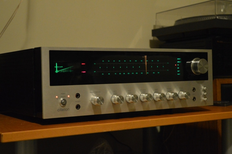
I normally don't post much about gear anymore but I thought I'd share this one. SN 296, was a local trade, ak member-I won't mention names but it was one of two that he has. I got the cosmetically challenged of the two but really it's not that challenged, just the more "used" of the two. It's rumoured that less than 1000 of these were made, more like 750. It would be nice to know of there is a sn higher than 1k, the other one was in the 300's.
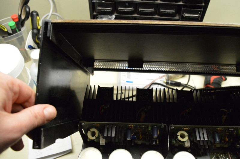
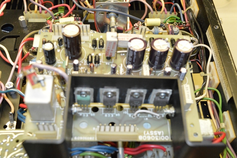
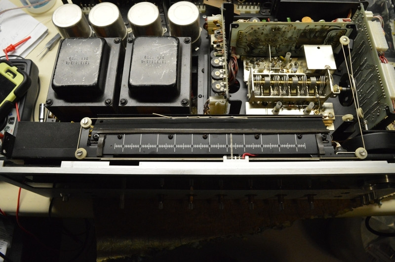
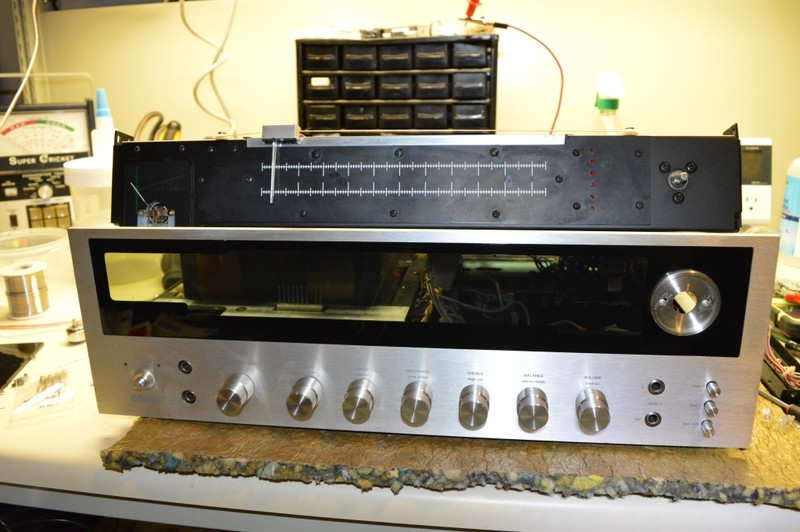
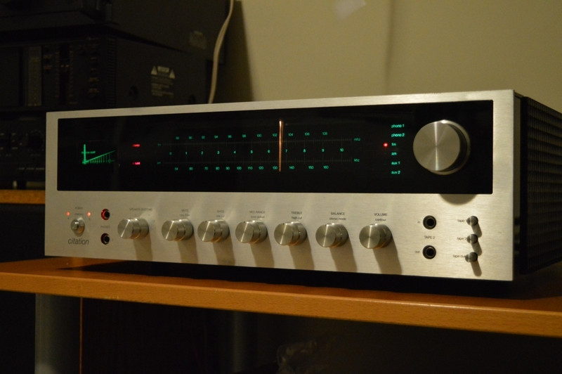
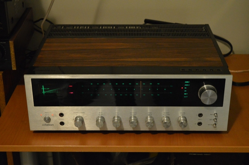
Few observations- this receiver is a double edge sword. It's beautiful, it sounds amazing, it's heavy, it's well built, it's cosmetically a work of art. The lid alone must weight 5 lbs if not more. The entire cover less the wood, which by the way no two units are alike by wood pattern design , is made entirely of steel. It's a dual mono power supply design, something you don't see often in a receiver. It has touch control inputs- revolutionary for it's time. I could go on and on about what it is.
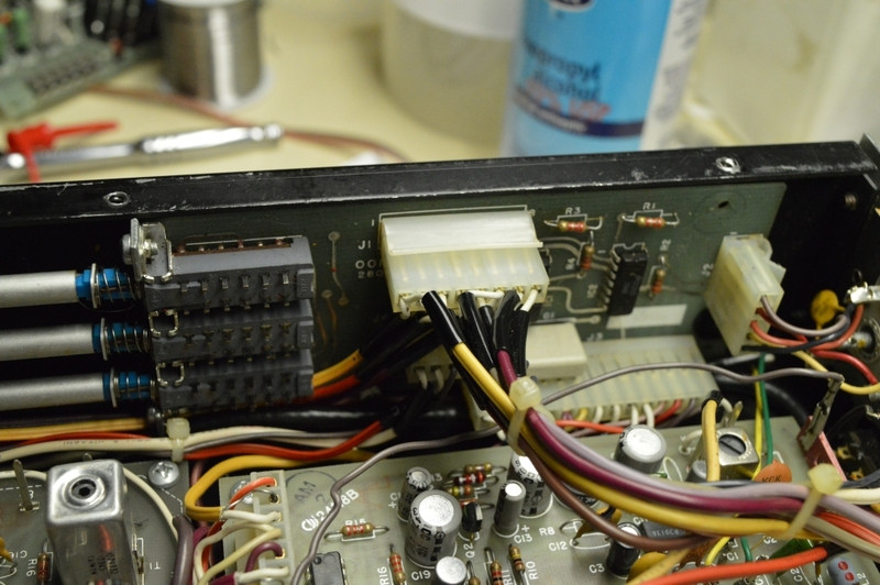
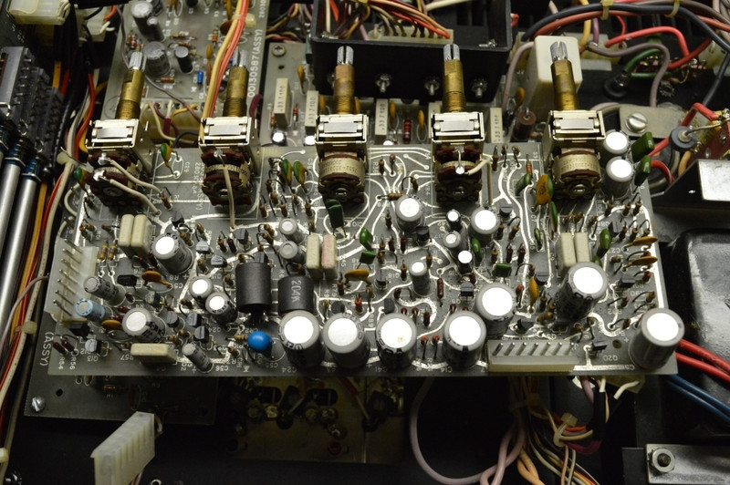
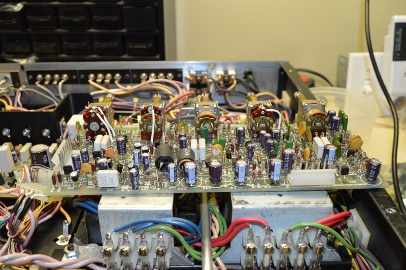
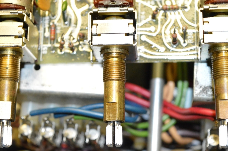
The other edge of the sword- not many were made making parts almost impossible to find. The service manual doesn't list the "real part numbers" of what was used- instead you get HK numbers and these numbers are only found in the citation. The touch control is made up of 12 or so IC's- going to be hard to service if something goes wrong, not only that, there are 3 connectors with approx 30 wires going to this one board- broken wire anyone? The pots are combo pots AND switches. Every pot you see also has a switch associated with it to do different things. Take the midrange pot for example, it also is responsible for turning off the tone controls. Need a replacement- good luck! And to make matters worse, every pot has a different part number! Needless to say I won't use it as a daily driver but I am considering making it my office receiver.
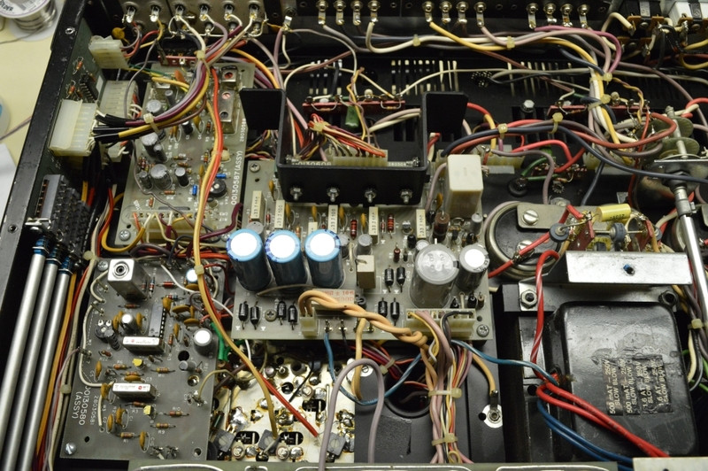
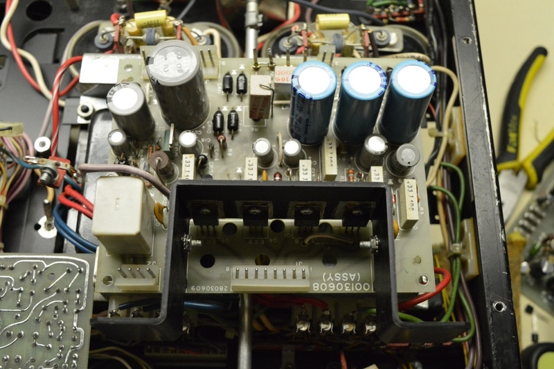
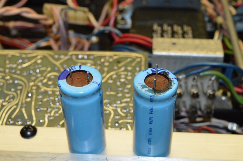
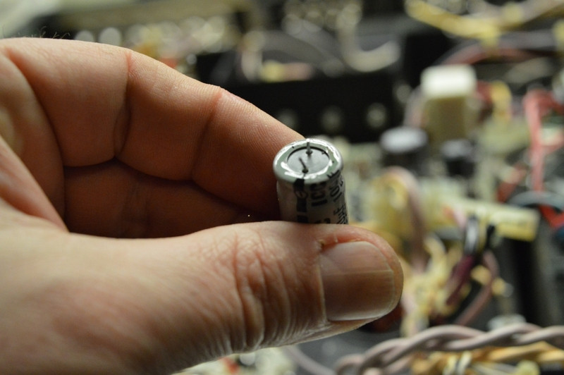
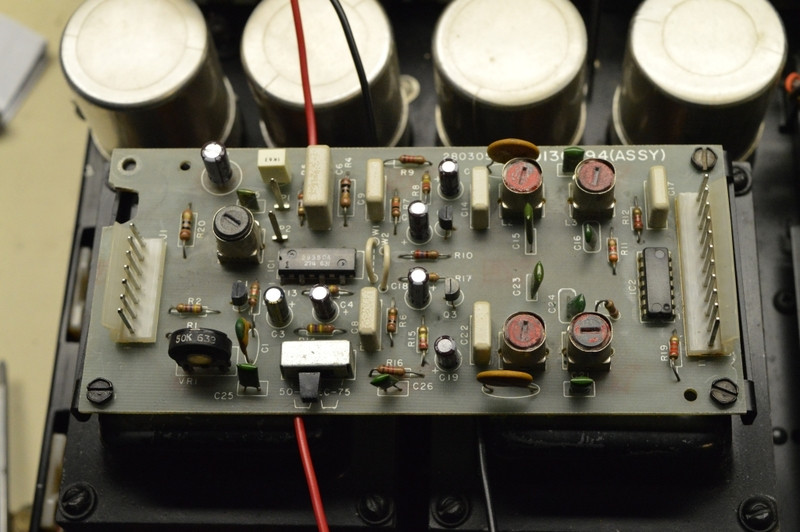
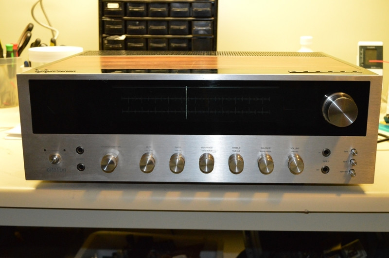
I spent the last 2 days recapping the PS/pre and mpx/muting board. Still have the FM IF board to do, i'm in no rush. I took a pile of pics I thought I'd share.
Few observations- this receiver is a double edge sword. It's beautiful, it sounds amazing, it's heavy, it's well built, it's cosmetically a work of art. The lid alone must weight 5 lbs if not more. The entire cover less the wood, which by the way no two units are alike by wood pattern design , is made entirely of steel. It's a dual mono power supply design, something you don't see often in a receiver. It has touch control inputs- revolutionary for it's time. I could go on and on about what it is.
The other edge of the sword- not many were made making parts almost impossible to find. The service manual doesn't list the "real part numbers" of what was used- instead you get HK numbers and these numbers are only found in the citation. The touch control is made up of 12 or so IC's- going to be hard to service if something goes wrong, not only that, there are 3 connectors with approx 30 wires going to this one board- broken wire anyone? The pots are combo pots AND switches. Every pot you see also has a switch associated with it to do different things. Take the midrange pot for example, it also is responsible for turning off the tone controls. Need a replacement- good luck! And to make matters worse, every pot has a different part number! Needless to say I won't use it as a daily driver but I am considering making it my office receiver.
I spent the last 2 days recapping the PS/pre and mpx/muting board. Still have the FM IF board to do, i'm in no rush. I took a pile of pics I thought I'd share.
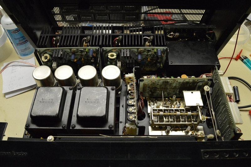
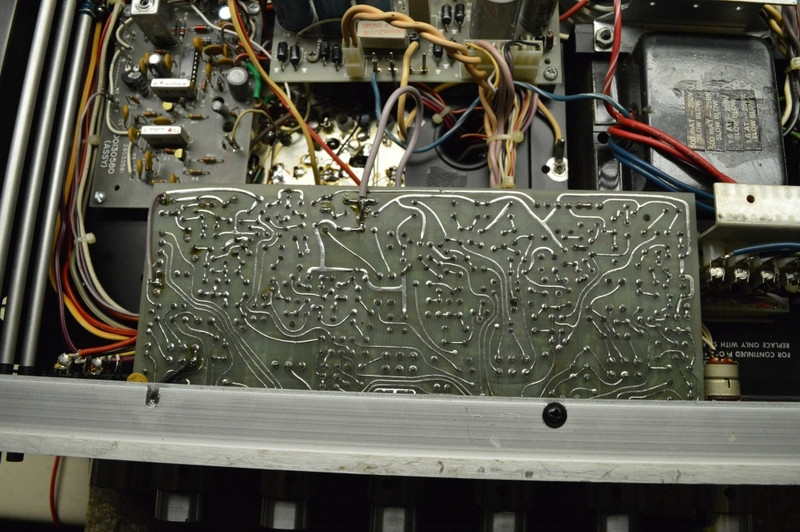
 . The touch control board is to the right of the tuning cap.