Pioneer SX-750: Both Channel Crack/Popping

yapo

New Member
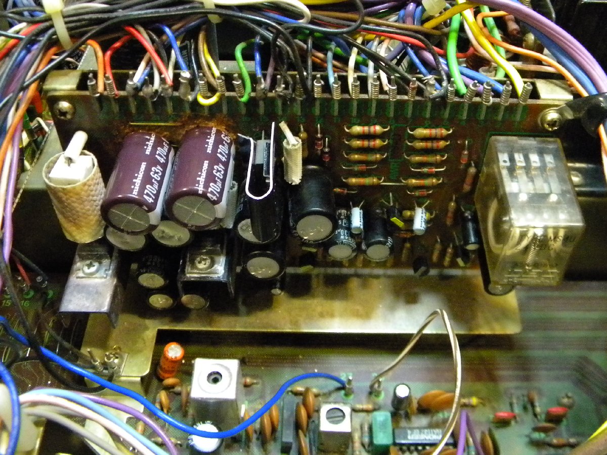
Hello, i'm new here, first post: i'm from italy and i apologize for my bad english: i hope someone will help me in fixing this amazing receiver. I refer to the post of BFried member ( http://www.audiokarma.org/forums/showthread.php?t=572125 ) that reports a similar issue. But i have something different: the noise at both channel. After 2 minutes of good sound, no matter the input or output ( aux, phono, tuner.....headphones or speakers ), no matter volume, tone or any controls, cracking and popping appears for 5, 10 seconds and finally the relays cuts off signal. If i power off and on the unit the problem repeats. So, i have deoxided EVERYTHING, but no results. Following the the speculation of BFried old post i thnink the problem is in the power supply and protection assembly. I test voltages with both digital and analogue instruments. This is what i found: on power supply AWR-100 nothing strange, all voltages are between 1% tolerance with schematics, fuses ok. So i went up on AWR-099 power supply and protection assembly and i found this:

Q8: SCHEM. 30V, READ 30V TO 26V VARIABLE ON FM INPUT, 40V STABLE ALL OTHER INPUT, ON LANE 22, READ 12,4 V ALL INPUT
Q3: SCHEM. 13,5V, READ 13 V STABLE ALL INPUT
Q10: SCHEM. 46V, READ 43,5V TO 47,5V VARIABLE ON FM INPUT, 46V STABLE ALL OTHER INPUT, ON LANE 23, READ 32,2V STABLE ALL INPUT
Q11: SCHEM. 34,4V, READ 32V STABLE ALL INPUT,
SCHEM. 14V, READ 14V ALL INPUT
Q12: SCHEM. -35V, READ -38V STABLE ALL INPUT
- SCHEM. -48V, READ -48V STABLE ALL INPUT
Q7: SCHEM. 12V, READ, ON POWER ON, 30V PEAK WITH ANALOGUE MULTIMETER, SLOWLY FALLING DOWN TO 8,3V, ON POWER OFF PEAK UP TO 18V, THEN GO TO ZERO, WITH ALL INPUT
- SCHEM. 12,5V, READ 8,3V STABLE ALL INPUT, NO PEAK
Q6: SCHEM. 13V, READ 8,9V, STABLE ALL INPUT, NO PEAK
-SCHEM. -1,5V, READ -1,5V, STABLE ALL INPUT, NO PEAK
ALL OTHER Q'S VOLTAGES ON BOARD ARE STABLE BETWEEN +/- 5%

NOTE: Q8 and partially Q10 runs VERY hot rising up from power on until i power off.

All voltages are read with 235v ac.

The unit is all original, no service jobs inside, everything in power amp runs cold, the caps are externally all good, fm, am and all other input sounds very good until cracks appears

Someone will help me ? I have no ideas for such a lot of strange voltages... i suspect q8, q10, q6, q7 or some bad cap or diode around these... but before working with solder on components i prefer to ask you for any help. Note: i work usually with tubes circuits, i have little experience with transistors.

Thanks for your patience.
 
watch the Q8 Q10 regulated voltages (+13 on awr-099 pin 22) (+34 on awr-099 pin 23) continuously during power up and watch and wait for the crackling and popping to happen and see if there is a relationship between the power supply voltages and the crackling and popping. ALso watch the -38v on awr-099 pin 17.

IF both channels are doing the crackling and popping THE SAME then it is a power supply problem.

If the regulated voltages are stable at this time, then watch the unregulated +/- 41 V DC on awr-100 pin 6 and pin 7.

We need to see if the noise is coming form the preamp sections, since there are no preamp out / amplifier in jumpers we must short the audio inputs for the power amps.

AWH-046 short pins 26 abd 27 for the right channel and pins 30 and 31 for the left channel and see if the pops are heard.
 
Thanks for the help. I test all the pins you said, but nothing to say, voltages are stable even during crackling and popping. BUT the problem starts to randomize itself: the output becomes stable or unstable. Last night the unit works good for an hour, this morning noise appears a little after two minutes but the relays doesn't cut off signal, now relays cut off well as soon as noise appears. The noise are THE SAME in both channel. The wrong voltages in the AWR-099 are still the ones reported in the first post in every situation ( good working or noise problem ). So what i should think ? A damn intermittent fail....
 
AWH-046 short pins 26 and 27 for the right channel and pins 30 and 31 for the left channel and see if the pops are heard.

Short these pin pairs together at the same time, and see if the pops continue. They are the inputs to the power amplifier and this will tell us if the crackling and popping is coming INTO the power amplifiers through the audio, or if it is being generated BY them.

Look at and describe (post a picture?) the type of package the power amplifier awh-046 transistors Q3 and Q4(2sc1438?) are as well as their actual part number. They will either be small and rectangular with a metal tab, or quite uniquely round with what looks like a heat sink attached as part of the device.

You have not told us what the DC offset voltages for the power amplifier outputs are, and if they stay stable in between crackles, also measure and watch the idle current for each channel.

Connect a speaker between the + for the left channel output and the + for the right channel output and tell us what you hear when it is crackling.

We REALLY need to know if this is a common mode problem occurring equally in both channels or not.
 
Last edited:
Well i have some news: as they come, the noise magically disappears.... the unit sounds good for almost four days. BUT the wrong voltages still remains in the awr-099. I took all the requested measurements on AWH-046.

Q3 and Q4 are 2sc1438b, in a TO-92 package
Offset voltages after 20 minutes: 51,8 mv Rch, 47,6 mv Lch
LINE 32: SCHEM. 35V, READ 32,4V
LINE 29: SCHEM. -38V, READ -38,2V
LINE 25: SCHEM. 35V, READ 32,4V
41 AND -41 VOLT LINES ARE OK.
LINE 21: SCHEM. 21V, READ 20,8V
LINE 28: SCHEM. -19V, READ -18,9V
Q2: SCHEM. 0,6V, READ 0,65V
Q3: SCHEM. -33,4V, READ -36,7V
Q4: SCHEM. -33,4V, READ -37,2
Q5, Q6, Q7, Q8: BETWEEN 0,05V TOLERANCE

I don't know how i can measure and watch the idle current for each channel: can you help me in this ?

Since there are no more noise, shortening inputs has no effect

I notice this:
1) some voltages becomes unstable ( see first post ) when i listen to FM broadcast using 32 or 600 ohm headphones, but becomes stable when using 8 ohm speakers
2) Q8, and partially Q10, heatsink runs hot as a volcano in all mode ( UNTOUCHABLE ! )
3) you can believe i'm crazy, but without speaker or headphones connected, when i put volume knob at 2/3 or full throttle, i can hear the music from relays !!!
 

Attachments

  • 20150117_143749[1].jpg
    20150117_143749[1].jpg
    55.5 KB · Views: 26
i'm from italy and i apologize for my bad english:

Welcome Aboard!

If you are FROM Italy, where are you now? ;)

I'm not from Italy, and I have no excuse for my bad English. You're doing quite well.

As for the power supply voltages, in the KC/KU versions of the SX-750, Pin 33 is shown as having 33V, not 35. Your measurement of 32.4 should be sufficient, and is within 10% of the design voltages on either schematic.

On the AWH-046, Q3 and Q4 voltages may change somewhat with offset adjustment. Both of your channels' output offset voltages also seem a little high.

As for the transistors on the AWR-099 operating hot, Q10 passes a considerable amount of current, and is designed for the purpose. However, refreshing the heat sink silicone grease (thermal compound) and possibly enlarging the heat sink for that transistor might be beneficial. That device supplies power for much of the unit.

The factory service manual is specific in its instructions for checking and adjusting the idle current. It is assumed that grabber-type test leads would be used to connect the meter while adjusting the settings.
 
A few new filter caps and devices on the power supply board are usually a good idea on these units. This is a view of one of my 750s with a rebuilt power supply and showing a clip-on heat sink for that very same kind of problem:

SX-750PSView.jpg
 
Ah, thanks for wellcoming. I live in north italy.
I beg your pardon i ask for something on your picture: is the last contact on the left of relays in wrong place ? It seems to be far away from the bay...
 
I have an acquaintance in Mantua. Other than the periodic earthquakes it sounds like a great place to live.

You reported earlier that on the AWR-099 power supply board:

Q6: SCHEM. 13V, READ 8,9V, STABLE ALL INPUT, NO PEAK
-SCHEM. -1,5V, READ -1,5V, STABLE ALL INPUT, NO PEAK

Q7: SCHEM. 12V, READ, ON POWER ON, 30V PEAK WITH ANALOGUE MULTIMETER, SLOWLY FALLING DOWN TO 8,3V, ON POWER OFF PEAK UP TO 18V, THEN GO TO ZERO, WITH ALL INPUT
- SCHEM. 12,5V, READ 8,3V STABLE ALL INPUT, NO PEAK

Depending upon which leads of Q6/Q7 you are reading, the voltage you report could be correct. For example, for Q7, the initial collector voltage should be something close to 33V since the transistor is not conducting. Once the protection circuit is satisfied and the transistor is biased to conduct, the voltage drop between the relay operating coil (which Q7 is driving) and the 220Ω emitter resistor should result in about 8V at the collector, or 24V across the relay operating coil.

When the unit power is turned off the transistor Q6 turns on to rapidly bleed off the 220µF capacitor and shut down Q7 to turn off the relay. This can result in the peak voltage you are measuring at that device.

If you translate (if necessary) and read the service manual Pages 16 & 17 they provide a description of how the protection circuit functions, and thus may explain the voltages you are reporting.
 
HI, thanks to watthour. The 8V readings leads are where manual says about 12v: i understand the schematics but my voltage are 40% less. It seem too much for considering beneath normal tolerance.... However i decide to close the cabinet and try to load the unit with 3-way 8 ohm speakers for about two hours and see what happend. The system sounds good with no more noise, crack or pop, but i notice the heat amount in the upper face of wooden cabinet: as you can see from the photo attached, there is the normal little heat coming from the 3 dial lamps, then a considerable heat in the wood just over the Q10 heatsink. So i 'd like to know if someone else who use the SX-750 has noticed this heat zone or it is due to the "my faulty something" that overheat the Q10.
Note that i desoldered and tested every component in the awr99, expecting to found almost a broken diode or shorted cap, but everything works fine. So, knowing if the upper amount of heat is normal or not, is important for me to decide if investigate again or consider my unit good. Thanks to everyone for helping me in this little test. Bye.
 

Attachments

  • SX750 UPPER CABINET TEMP.jpg
    SX750 UPPER CABINET TEMP.jpg
    93.2 KB · Views: 31
heat on q10: read the voltage across R33 (10 ohms??? OR 33 ohms???)

Report the color code, there is disagreement in the service manual -
one place in the manual it says 10 ohms (brown black black gold),
in other places it says 33 ohms (orange orange black gold).

the schematic indicates 30mA current draw AFTER the protection circuit,
and the relay should draw about 37mA (call it 40 for extra current to run the protect circuits themselves)
for a total of 70mA current draw.

-----------------------------------------------------------------------------------------
70ma Through a 10 ohm (brown black black gold) resistor should have 0.7 volts across the 10 ohm resistor when the voltage across the resistor is read:
put the red DMM probe on one lead of the resistor,
put the black DMM probe on the other side of the resistor at the same time,
INSULATE all but the smallest portion of the end of each probe tip with "scotch tape/ office tape".

Report the voltage, if it is around 0.7 volts you are fine.

Since R33 is a 10 ohm 1/2 watt resistor, at 2.2 volts (220mA) it would be at maximum dissipation, any higher of a voltage would destroy the resistor

------------------------------------------ or ----------------------------------------------
70ma Through a 33 ohm (orange orange black gold) resistor should have 2.3 volts across the 33 ohm resistor when the voltage across the resistor is read:
put the red DMM probe on one lead of the resistor,
put the black DMM probe on the other side of the resistor at the same time,
INSULATE all but the smallest portion of the end of each probe tip with "scotch tape/ office tape".

Report the voltage, if it is around 2.3 volts you are fine.

Since R33 is a 33 ohm 1/2 watt resistor, at 4 volts (120mA) it would be at maximum dissipation, any higher of a voltage would destroy the resistor
-----------------------------------------------------------------------------------------

as far as a hot spot, you can't just blame Q10, the whole power supply is contributing to that hot spot.

the lamps are 8v at 300ma which is 2.4 watts apiece

the power supply heat budget at a glance:
Q10 is dropping 46 volts down to 34 volts (12 volts) with 70mA of current, that is 0.84 watts.
R29 (150 ohms 5 watts) is dropping 48 volts to 30 volts (18 volts) at 120mA and that is 2.16 watts
Q8 is dropping 30 volts down to 13 volts ( 17 volts) at 120mA and that is 2.04 watts

and there are other heat sources on it, so comparing the power supply at 5 watts and 2.4 watts lamps shows it is NOT unusual.

all a hot to the touch q10 heat sink means is that (IF the current is reasonable) the heat sink is a bit small for the power dissipated.
 
Last edited:
No help here. All the photos I have clearly of my several units show the fiberglass sleeve over that resistor, making it impossible to get a visual confirmation.

That said, I'd guess R33 on the AWR099-D is 33Ω based upon the 2V drop to the collector of Q10 at an assumed 70mA (it comes out to 28Ω if you're splitting hairs). That means about 1/8W dissipated, which isn't unreasonable, but would generate heat.

If it were 10Ω the 2V drop would indicate something more like 200mA representing nearly 400mW continuous, or quite a lot to design for a ½W resistor.

Further, while the individual board schematic and board artwork both indicate 10Ω, the factory BOM and the complete schematic for the KC/KU type are marked "33Ω" quite clearly.

Pioneer documentation strikes again...
 
Thanks for your help. I can confirm that r33 is 32,7 ohm: see the attached img. for other specs. But i apologize becouse i made a mistake, the hottest heatsink is the Q8's one, i swap them due to distraction. I read the datasheet of 2sd313 ( 30 watt max power dissipation and 150 c degrees max temp ) and i begin to think that pioneer guys simply used an ugly heatsink for this work becouse the hottest one reaches its own temperature and maintain it until the unit is powered down. I'd like to know what do you think about it... and about the different voltages i see on Q8: manual says 30v on R29 side, but it is true only in FM mode; in AM, Phono and Aux i found 38v, that is widely among the 2sd313 range but out of specs for the manual. What should i think ? From AWR-100 there is correctly 46/47v on line 18 stable in all mode, included FM, and line 22 in AWR-099B are stable on 12,6v all mode, included FM, so i think that Q8 is doing its work well nevertheless. Someone knows what is the current drain from the line 22 ? I can't find it on service manual. Thanks !
 

Attachments

  • R33 Q10 AND Q8.jpg
    R33 Q10 AND Q8.jpg
    109.7 KB · Views: 29
Hi again, after weeks of tests i found this: the voltages on Q10 and bias becomes unstable ONLY with headphones, ( tried from 32 to 600 ohm ), plugged into jack and no loudspeakers connected on rear. Headphones two resistors and wires checked good, contacts deox and cleaned. Is it normal ? Some ideas ? Thanks.
 
Q10 is the 33V supply regulator. It supplies the FM muting board and microphone pre-amplifier, power amplifier, and protection section. With the power amplifier only driving headphones, it is understandable that the decrease in load might allow for voltage variation. However, the voltage should regulate within a few percent. If the incoming 48VDC supply to that part of the circuit varies, and for overall stability, it would be a good idea to replace C17/C18 with 63V rated capacitors in those positions. This is safer than replacing them with the original 50V rated parts since the circuit operates very close to that 50V potential.

Q8 is the 13V supply regulator. It will conduct more current when the 13V supply is loaded with the FM tuner section front end active (power switched through S1) than it will when only AM is selected. The lighter loading may be allowing the collector voltage on Q8 to float up when FM is not active. Since the 13V supply output at Pin 22 is stable, the section is doing its job to regulate power. The transistor does operate hot, and refreshing the silicone thermal compound can help transfer heat. Enlarging the heat sink can also help. Keeping the area clear of wire bundles and moving the 5W resistor (R29) as far away as possible so that air can flow through will also be helpful.
 
Back
Top Bottom