

You are using an out of date browser. It may not display this or other websites correctly.
You should upgrade or use an alternative browser.
You should upgrade or use an alternative browser.
SX-1250 problems again
- Thread starter Yamahaha
- Start date
Spend the $$$ and get some new pots. Less than $10.00 plus shipping. The originals are open and collect junk faster than a homeless person. Plus you run the risk of having an open in the winding from it sitting so long in one position, which can result in a catastrophic loss. Get some sealed Bourn's (single or Multi turn, you're choice) and reset it all. Set the BIAS to 75mv as TSD71 recommended. The ones you need should be on the recap list's. Or one of the 1250 owners will put up what they used.
Larry
Larry
This morning I returned to the 1250 and the relay issue has not happened once. My OCD did kick in to set the bias and I have 88mv offset both sides and my bias is now 3mv R and my meter jumps from 1 to 2 mv L. I did not enjoy adjusting with the factory pots. The stabilizer board is 65mv
I guess the cleaning I did solved the issue and that last bit of dirt dislodged. Will be monitoring it this weekend. I am glad the relay problem went away but sure would like to know why.
I am tempted to set DC to 100mv as spec. Any benefit or am I wasting my time?
Your OFFSET TARGET is 0.000v as referenced to a bare metal chassis ground. That's the red dmm probe to pin 9 and the black dmm probe to a bare metal chassis ground reading.
Your IDLE CURRENT should be 100mv or 88mv or 75mv. That's the reading with the red dmm probe on pin 7 and the black dmm probe on pin 19.
While measuring IDLE current MAY NOT MAKE SENSE BECAUSE YOU ARE READING volts, THEY ARE volts ACROSS A CERTAIN KNOWN RESISTANCE (two 0.5 ohm resistors in series), which translated through ohm's law, to a current.
The stabilizer board reading would be 65 VOLTS.

Last edited:
Yamahaha
Well-Known Member
The stabilizer board reading would be 65 VOLTS.
Yes you are right again. Thanks Mark.
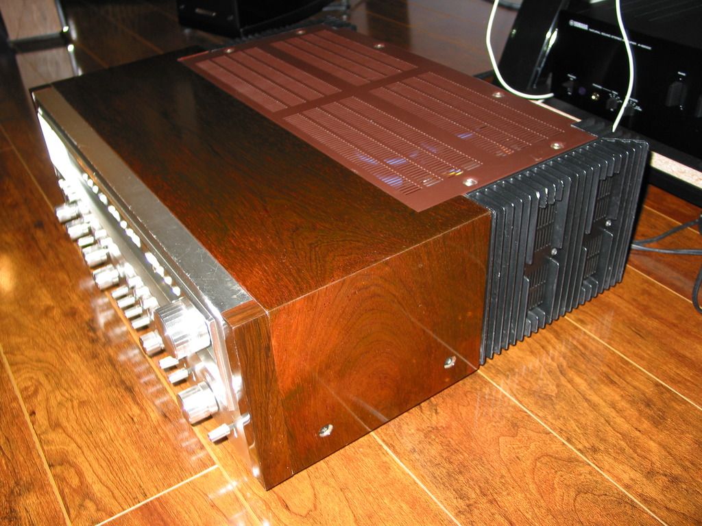
Since I haven't been able to get this to choke again I have sanded the case and am prepping a slice of Brazilian rosewood to be the new veneer. Will add some nice new solid pieces on the front sides and it should look slick. Not that there's anything wrong with walnut. But I like Rosewood better. And Brazilian smells good.
Yamahaha
Well-Known Member
this is so frustrating .. I get it on the bench and it works again.
Would the relay itself cause this? When last it failed I wasnt running anything. It was on, volume down simply resting and I heard the click. Then no matter how many times I powered on and off it wouldn't come out. It was in my audio rack. SO I take it out and now today - it works again. Powers up like normal.
When I was running it there was no problems. Sounded good. Didn't hear any crackling or distortion. It did not even run hot. Warm at best.
Last edited:
The 1250 has many potential problem spots: each and every PC board pin to connector connection. They can become intermittent and maddening. That's why I polish up the pins and then deoxit the heck out of them and the connectors. Concentrate 5mm and up from the board on each pin, as that's where the contact starts in each connector.
Having reread the whole thread, I cannot believe that I (or anyone else) didn't ask (or mention deoxit):
WHAT are you using for cleaning?
IF you weren't using Deoxit, you were just cleaning the corrosion, cleaner doesn't touch the oxides and sulphates of corrosion. Deoxit loosens their bonds so that the friction of repeated actuations scrubs a LASTING (years, not days) clean path for the contacts.
Can't be the relay.... relay only follows directions.
we now enter the troubleshooting phase.
first: initial conditions.
WHICH transistors and capacitors have been changed?
It could be the power supply cutting out, either amplifier channel misbehaving or the protection circuit mistriggering (operating when NOT needed).
Or as simple as the relay driver transistor being original and tired. IF the relay driver transistor is new, that's ruled out.
Yamahaha
Well-Known Member
This is tricky. I hired 2 "professional" shops. One did the first overhaul/recap, the second replaced transistors - twice! in different sections.
So I don't know exactly what they did. Its obvious the Nichicon golds etc are new. The big cans again obvious. Other little parts were swapped but I am not knowledgeable like you guys at electronics. I have a baggie old old parts. I suspect the 3 legged transistors that I can see are old. Corrosion up the legs.
I have $800 in repair shop bills, 3 round trips. I was thinking of replacing the transistors on the board with the relay. They are again corroded up the legs. I know these parts are cheap. I just don't know how to find the proper replacements.
We know the replacements.
Post a list of the transistors in the bag, that's a good start.
The board with the relay, are all transistor's legs blackened? What are the numbers on the transistors on it now?
That's the protection board, it is easy to upgrade, and should be done first. We can tell you which transistors to get and where to get them.
Do you have the 64MB "hi-res" service manual? If not, get it.
It is the road map to the unit.
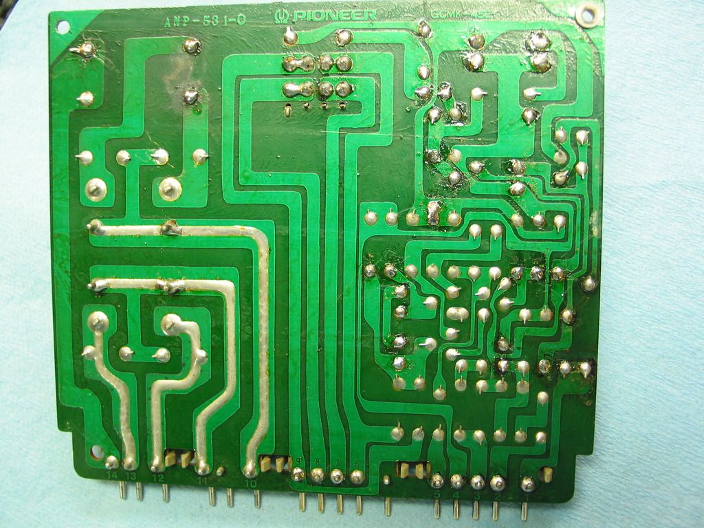
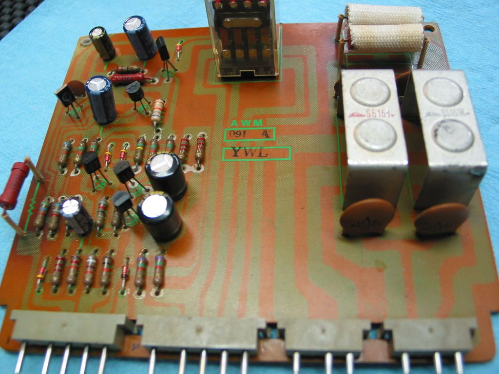
boards are referred to as awm-091 (the protection board) and q1 through q6 (the transistors).
The rest of the protection circuits are on each (awh-048) amplifier card, and communicate through pins 1 of the two (left and right) (awh-048) amplifier cards and pin 5 on the protection board.
when we are done with this board, it definitely will be eliminated as the cause.
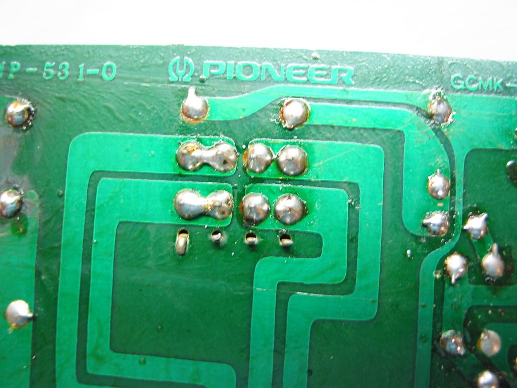
If you can post a picture of the protection board, it will assist the cause.
Post a list of the transistors in the bag, that's a good start.
The board with the relay, are all transistor's legs blackened? What are the numbers on the transistors on it now?
That's the protection board, it is easy to upgrade, and should be done first. We can tell you which transistors to get and where to get them.
Do you have the 64MB "hi-res" service manual? If not, get it.
It is the road map to the unit.
boards are referred to as awm-091 (the protection board) and q1 through q6 (the transistors).
The rest of the protection circuits are on each (awh-048) amplifier card, and communicate through pins 1 of the two (left and right) (awh-048) amplifier cards and pin 5 on the protection board.
when we are done with this board, it definitely will be eliminated as the cause.
If you can post a picture of the protection board, it will assist the cause.
Last edited:
Yamahaha
Well-Known Member
Awesome, thanks Mark. I had a blurry version of the SM. This ones much better.
I will post a list of parts. The unit is stuck in protection again. Where should I be taking measurements with the MM? Is there any "smoking gun" to narrow where the problem may be while its in protection?
The measurements are just lightly different from last time.
Stabilizer board is 64.3 and 63V (was 65)
DC offset 92 and 94mv (was 88 before)
speaker out reads 0 ... which was 1 and 3mv before
Last edited:
DC offset of 92 and 94 mV means the amplifiers are NOT misbehaving. As long as the protection continues suppress the relay AND you are probing a spot that isn't disconnected when the relay is suppressed.
Yes there are "smoking guns".
Can you measure pin 5 of the protection board when it is in protect, it is also pin1 on each of the amplifier cards. That is the over-current sense on each amplifier card, and can (q11, c11) falsely trigger.
This measurement will be a BIG help in determining the culprit, by establishing it's innocence.
Look at each amplifier card, for C11, is there a small sky blue sanyo in it's place? It will be found next to a group of 4 (fabric covered) resistors in a row on one side of the board. When in doubt, use the manual to see where it is, to visually identify it.
Once that cap and pin 5 voltage issue is resolved, then we will check for the "smoking gun".
That is the relay drive signal. If it says "pull in the relay" and the relay doesn't pull in, well..... that's big.... It's q5 base.
The easiest access is at C4's positive terminal, c4 is the 100uf 16v cap on the CORNER of the board. The positive terminal is closest to the outside edge.
When it is trying to turn on when the relay is NOT pulling current, any voltage over 0.6v says "turn on". AFTER relay current flows, that voltage will rise to 10 volts or so because of the effect of the relay current THROUGH R20 (220 ohms 1 watt) which raises the emitter to (for EXAMPLE) 10 volts. THEN 10.6 volts is needed at the base of Q5 to KEEP q5 turned on.
But all you have to do is measure the voltage at the + terminal of C4.

Yamahaha
Well-Known Member
Pin 5 of the protection board measures 4.5 V although it seems quite erratic. I've gotten 4.5, 6 ... jumpy. got a chirping sound when the measurement goes erratic (a few times, not always).
Pin 1 of the power boards is 0
The two red "resistors"? R24, 25 on the protection board that are covered on cloth sleeves are quite warm to the touch. With the power off R 24 reads using continuity end to end ... R 25 does not. This shouldn't read open should it?
Pin 1 of the power boards is 0
The two red "resistors"? R24, 25 on the protection board that are covered on cloth sleeves are quite warm to the touch. With the power off R 24 reads using continuity end to end ... R 25 does not. This shouldn't read open should it?
Last edited:
Lift one leg of D3 on the protection board, it is connected to pin 5.
Looks more like q11 is leaky on one of the amp cards. If the protection triggering STOPS, we will know.
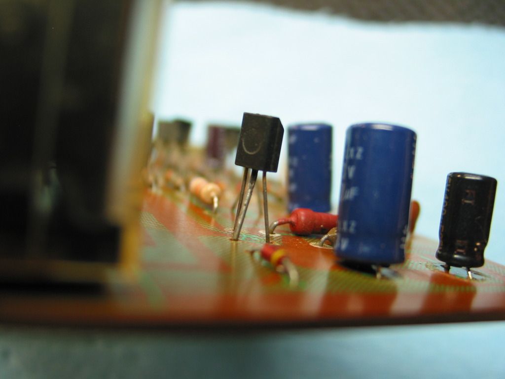
When I asked for:
I meant the currently installed transistors on the protection board, what are their parts numbers identifiers that are printed on each of them. I NEED to know that relay driver's number, the picture doesn't show it.
The way pin 5 works is that it should be sitting at 18 volts or more, and pulling it down past 17.3v triggers the over current protection.
6v says q3 could be damaged as well, if pin 5 wasn't pulling current.
The voltage reading after d3 is lifted will start to tell. That point is connected to +35v through a 150,000 ohm resistor.
Quite frankly, at this point I shotgun c11 and q11 on both amp boards, and all caps / transistors on the protect board and not waste any more time on it.
Looks more like q11 is leaky on one of the amp cards. If the protection triggering STOPS, we will know.
When I asked for:
Post a list of the transistors in the bag, that's a good start.
The board with the relay, are all transistor's legs blackened? What are the numbers on the transistors on it now?
I meant the currently installed transistors on the protection board, what are their parts numbers identifiers that are printed on each of them. I NEED to know that relay driver's number, the picture doesn't show it.
The way pin 5 works is that it should be sitting at 18 volts or more, and pulling it down past 17.3v triggers the over current protection.
6v says q3 could be damaged as well, if pin 5 wasn't pulling current.
The voltage reading after d3 is lifted will start to tell. That point is connected to +35v through a 150,000 ohm resistor.
Quite frankly, at this point I shotgun c11 and q11 on both amp boards, and all caps / transistors on the protect board and not waste any more time on it.
Last edited:
Ok, waiting upon the results of operating without D3 having BOTH leads connected for a while - defeating the over-current protection circuits (so be careful about speaker loads and wires).
New relay - nice
Q5 original... we'll see...
New relay - nice
Q5 original... we'll see...
Similar threads
- Replies
- 16
- Views
- 1K
- Replies
- 9
- Views
- 827