Nikko Alpha 440 repair with schematic

Smwilli

Well-Known Member
Hi all.

I recently picked up an Alpha 440 that doesn't work. It's in excellent shape and would like to get it up and running again. I hope to use it to replace my M504 on Boston Acoustics A400's.

I've done some trouble shooting and found that if I remove the 1amp fuse on the regulator board, the amp will come out of protect.

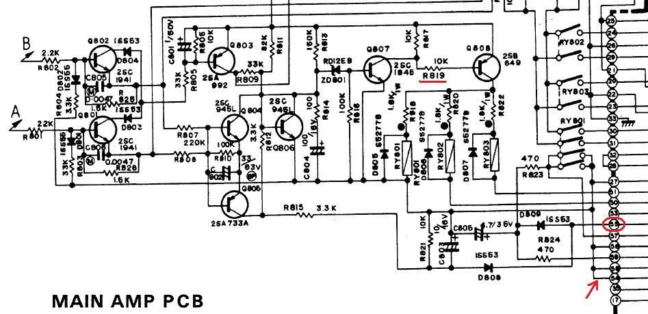
The one amp fuse feeds the single lightbulb for the meters as well as travels to the main amp PCB. I've circled number 55 on the schematic where that power enters the PCB. The associated ground is indicated with a red area.

Upon visual inspection, there is a resistor that has been replaced along with a scorched area right below it. (R819 underlined) I measured the resistor and it's open. I'm assuming that excessive current draw through the resistor is what a)killed the resistor and b)is the cause of the amp being in protect.

Is a good starting point to unsolder the components located around r819 and test them? I have one of those octopus testers and a scope to test the transistors and caps.

Any help or insight would be appreciated!

 
That is interesting so your two amp channels may still be okay which is a good sign.

So as it looks Q807 can switch Q808 only through this resistor, I guess it can not do any harm here just try replace the resistor. Was a small one put in an maybe you have an indication af the actual value what was sitting there? It could be the wrong value was in contributing to the failure, or a very low wattage one?

Indeed it could be handy test surrounding parts like the relay steering transistor q808.
 
Test all the transistors, resistors and diodes on the amp.
Make sure you get all the bad parts in the first order.

:thmbsp:
 
I'd love to help you but you probably know more than I do. As a long-time owner of an Alpha 220 which I've been very happy with, I'm interested in what you find out.
 
Alrighty, I found someone had tried to remove the cover of relay RY801 and cracked the PCB. I fixed the traces removed the incorrect resistor so far. Now I'll start testing the other components.
 
So far I've tested all the transistors (good), resistors (1 open, 1 out of spec, both circled in red), and am starting on the diodes. So far everything looks good. Do I need to test the rest of the main PCB components if everything checks out in the protection section I posted above?

I ask because I had to unsolder around 15 "plugs" so I didn't disturb the wirewrap to remove the board to work on it. I don't want to reinstall all the plugs and find out I have to re-remove it. Thanks for everyones help!


Okey Dokey. Round 2. Got everything buttoned up, started it up and r823 went up in flames (rather spectacularly). After I put out the fire, measuring across the resistor shows a short. All other components tested good. The resistor seems to be inline with relay RY801. I can post more of the schematic, but would the relay be suspect? It's a 48v coil, DPDT and the coil measured 2.83kOhm when I had it out. This is the relay that where the board was cracked.

Anyone have some direction for me? Thanks.
 
Last edited:
It also seems to run the protection indicator. It was working and lit before I replaced R817 and R819. Heres a pic for the run to the indicator:

 
Round 3. R823 burned up because I missed a broken trace at RY801. Now on powerup, either R819 or R817 opens up. I forgot to unplug the unit (but did have it turned off) and tested R817 for continuity and RY801 activated, something it hasn't done yet. Would Q807 or Q808 be suspect now?

I realise not everyone here is technically inclined (including myself), but I kinda feel like I'm talking to myself here.
 
resistors burning up says short circuit or high current draw for some reason .
looks to me like r823 supplies power to protect indicator whilst ry801 is off .then when ry801 is switched on it supplies power to s3 and when that's turned on switches on ry803 .
have you checked the diodes that go across the relay coils ? if one or more is short that is the problem
 
Can I make a small suggestion to run this up on a variac, or some other slow ramp techniques..
making fixes and powering on to sparks and flames only causes more faults.

Round 3. R823 burned up because I missed a broken trace at RY801. Now on powerup, either R819 or R817 opens up. I forgot to unplug the unit (but did have it turned off) and tested R817 for continuity and RY801 activated, something it hasn't done yet. Would Q807 or Q808 be suspect now?

I realise not everyone here is technically inclined (including myself), but I kinda feel like I'm talking to myself here.
 
Yeah I recently got a variac that I started using. I didn't know if it would work because it's only rated at 2 amps. When I tried it on the Nikko, it worked fine, just made sure to ramp up the voltage slowly.

Resistors R819, 817 don't burn up, they just "open" up when the unit is started. As for the diodes, I had tested all 3, but one tested odd on the octopus tester. At first it was a verticle line with a 45 degree horizontal section. I tested it again and got the correct verticle line with a 90 degee horizontal line.

I guess I'm not understanding why R819 and 817 are opening up (or how to correct it for that matter).
 

Attachments

  • dfdfd.jpg
    dfdfd.jpg
    2.7 KB · Views: 14
Last edited:
do R819 and 817 open up if speaker switch is off ? this might help narrow it down a bit .
i suspect a short by the relays or a bad transistor q808 or q807 .
 
Yes, everytime I've turned on the amplifier, the speaker switches have been off.

Another thing is that it's either 819 or 817 that open. 1st time I started it 819 opened. I replaced that, restarted and 817 opened. Replaced that and 819 opened again.

And thanks for your continued help. I really appreciate it.
 
those resistors are in series when going to q808 base .and they are same value so its a fight between them which one goes first .
pull q807 and q808 to test them first off .
 
The circuit is fed from 77Volts. Therefore if Q807 conducts, you have 500 milliwatts dissipated by BOTH (each of the) the resistors. Some 75 volts over 10k will be 7.5 mA and over 500 mW
IF Q807 would be shorted to ground, or being on by proper operation, the relay would be on, all times.
If Q807 is open, the resistors share 0.7 volts together, almost no dissipation and the relay is off.
If Q808 would be defective shorted, the relay would be on, all times.
If Q807 would be open to ground but have a short between base and collector, Q806 and 804 would be likely to fail also, because the 2sc945 VCe is specified max 50 volts.

The resistors should be 1 watt fusible types at least, as they can run hot.

Note: this so-called octopus testers can easily destroy or deteriorate small-signal transistors because of too much reverse emitter to base current. The same applies to Huntron trackers and alike in-circuit testers. Of course, depending on the settings/voltages/series resistance.
 
Last edited:
Back
Top Bottom