

You are using an out of date browser. It may not display this or other websites correctly.
You should upgrade or use an alternative browser.
You should upgrade or use an alternative browser.
Fisher FM 200 B Questions
- Thread starter monoethylene
- Start date
monoethylene
Active Member
Thats my idea")
Have you changed all three in order to the spec?
I want to change or add only one. This is easier
Have you changed all three in order to the spec?
I want to change or add only one. This is easier
Last edited:
Thats my idea
Have you changed all three in order to the spec?
and
I want to change or add only one. This is easier
You mean the resistors? I've only upped the first one (I don't know the exact value by memory however).
Happy to know that you're heading in the right way.
However, it looks they need to be aligned to perform at their best (I have another thread about mine where I states that I have a slight distortion in the bass region albeit I had recapped the unit entirely...).
monoethylene
Active Member
Yes, this was my first thought to add another resistor in series to decrease the voltage.
Concerning alignment, I am looking at a FM generator. The rest is in the laboratoy and I will try it myself..
Philipp
Concerning alignment, I am looking at a FM generator. The rest is in the laboratoy and I will try it myself..
Philipp
monoethylene
Active Member
OMF .. I ve just recognized that one tube as a slack joint..
Whenever I touch it it works..wonderful I think
Whenever I touch it it works..wonderful I think
monoethylene
Active Member
Has anybody measured the voltages of the tuner? I am a little bit astonished because I ve measured the voltage of the 1st 6AU6 at pin 5 and 6 and I got appr. 200v each. In contrast to the manual where it is written as 167.4v and 120v respectively. Further pin 7 has a voltage of about 0v in contrast to the expected 1.1v.
Further after the Fisher played the whole last night, right now I get a good signal but after a few seconds it fades away and last but not least..
when I press only a little bit at the chassis the signal is lost???? Does this pressing affect the capacity of the tuning section?
Here are some more pics of the unit


Cheers,
Philipp
Further after the Fisher played the whole last night, right now I get a good signal but after a few seconds it fades away
and last but not least..when I press only a little bit at the chassis the signal is lost???? Does this pressing affect the capacity of the tuning section?
Here are some more pics of the unit
Cheers,
Philipp
monoethylene
Active Member
It's me again
Here is a photo of the strange cap. The manual says 25uF 6v and this one is rated with 0.5uF 350v.
I replaced it right now with a 22uF 350v cap but am curious what the right value. Maybe this has to do with the different manuals for different serial numbers?
It would be kind,if anybody may chime in to give a hint. My model has a 50xxx+ serial and the manual I have says 30001-49999.
Cheers,
Philipp
monoethylene
Active Member

That's definitely strange. A .5uf electrolytic? I'll let the Fisher experts answer. I know that there's some that says that the real schematic is the actual unit under repair and one should replace with the values found...
But I'm not expert and don't want to give you a false information.
As for the lost of signal by pressing the frame, it could be a bad socket or a bad tube...or a broken solder joint.
Patrice
But I'm not expert and don't want to give you a false information.
As for the lost of signal by pressing the frame, it could be a bad socket or a bad tube...or a broken solder joint.
Patrice
monoethylene
Active Member
I will check the issue of loosing the signal this evening.
Despite that, I adjusted the voltages after the bridge yesterday and now these are fine within the spec..
Despite that, I adjusted the voltages after the bridge yesterday and now these are fine within the spec..
monoethylene
Active Member
Thanks a lot for your hints
Right now everything works perfect!!
One last picture

Cheers,
Philipp
Right now everything works perfect!!
One last picture
Cheers,
Philipp
thefragger
Certified Crazy.
Voilà, here is my new bridge. I will install it this evening as well as replacing the recommended caps

Have fun,
Philipp
Hi Philipp,
From what schematic did you build this circuit? I have started working on my Fisher R-200, but don't know what to do when I take out the selenium rectifier and when I put in a silicon diode bridge (what resistors to use to drop the voltage correctly)!
Thank you for any information, from another Philip!
monoethylene
Active Member
Hi Philip,
I ve taken the schematics here from AK. There you can find the schematic of the FM 200 B.
Have a look:
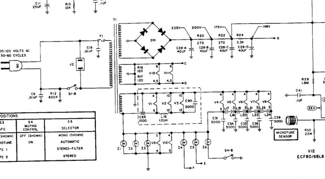
I ve just seen that your schematic can also be found there. First of all I would recommend to measure the voltages, this means to measure 138V, 110V, 90V and 22V.
When you want to replace the slenium rectifier by a silicone one, the voltages are normally higher. I ve had the same problem. Because of that, I ve placed a resistor in series just after the rectifier. It is easy to calculate the value and the you can reach the voltage (from the schematic) plus minus 5V.
Maybe this would help you, eventhough this is in german:
http://old-fidelity.de/thread-3087.html
Dont hesitate to ask, if you have problems. By the way, which selenium rectifier are inside your unit??
Have fun
Philipp
I ve taken the schematics here from AK. There you can find the schematic of the FM 200 B.
Have a look:
I ve just seen that your schematic can also be found there. First of all I would recommend to measure the voltages, this means to measure 138V, 110V, 90V and 22V.
When you want to replace the slenium rectifier by a silicone one, the voltages are normally higher. I ve had the same problem. Because of that, I ve placed a resistor in series just after the rectifier. It is easy to calculate the value and the you can reach the voltage (from the schematic) plus minus 5V.
Maybe this would help you, eventhough this is in german:
http://old-fidelity.de/thread-3087.html
Dont hesitate to ask, if you have problems. By the way, which selenium rectifier are inside your unit??
Have fun
Philipp
thefragger
Certified Crazy.
OH! I now understand what you did--you rebuilt the four-section capacitor under the chassis! Ok, I was not clear on that; I thought you built a special bridge to get the voltage down to the correct value!
My web browser (Google Chrome) automatically translates web sites for me into english
Thank you!
Philip.
My web browser (Google Chrome) automatically translates web sites for me into english
Thank you!
Philip.
monoethylene
Active Member
Exactly, I ve replaced the electrolytics as well as the resistors (RC network) and the bridge. First, I ve used a silicone bridge. There I ve adjusted the voltage by a power transistor in series. Later I ve got another NOS selenium bridge from another member and changed again the silicone bridge to stay original and vintage.
Have fun
Philipp
to stay original and vintage. Have fun
Philipp
Philipp; Keep that Silicon Bridge handy. Even tho that "new" selenium is supposedly "NOS" I'd keep a close eye on it. If it goes, it will spew toxic gases. Not pleasant in any case. FISHER DID change over to a Silicon Bridge late in production from what I've read lately. So the Silicon Bridge can be accurate as well as vintage.
Larry
Larry
monoethylene
Active Member
Thanks a lot Larry for this advice!! I will take care of course and more care when restoring tube audio gear. Further the PCB is easy to disassemble and so I can change the rectifier whenever I want. Right now it works beautiful but when I am going to sell the item I will say exactly your advices.
Cheers
Philipp
Cheers
Philipp