

The Fisher 660-A console amp I acquired recently is finally finished (other than a bottom plate - most likely I'll need to go to Front Panel Express for this). In the words of Han Solo, "She may not look like much, but she's got it where it counts, kid. I've made a lot of special modifications myself."
The top remains more-or-less stock. I added my favorite Pomona screw-in banana jacks to the speaker terminal strip, but the spacing was a little closer than desired. The solution was fishpaper (dielectric paper) strips cut, punched and glued then secured by the Pomona jacks. Also note the bias test points (red & black) on the wafer connector and the slide power switch. Tubes are original Fisher 7591 and Telefunken 12AX7 smooth-plates.
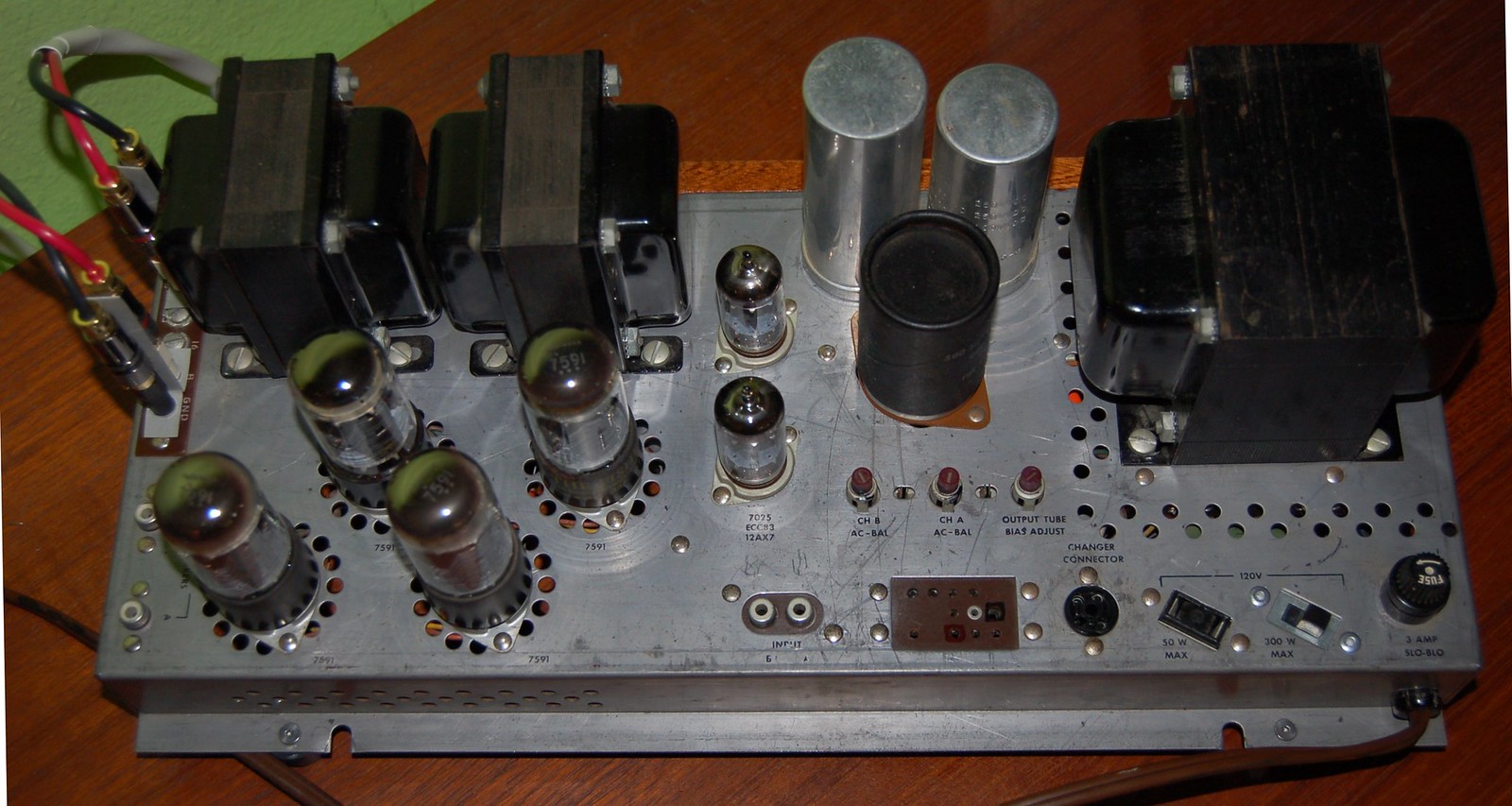
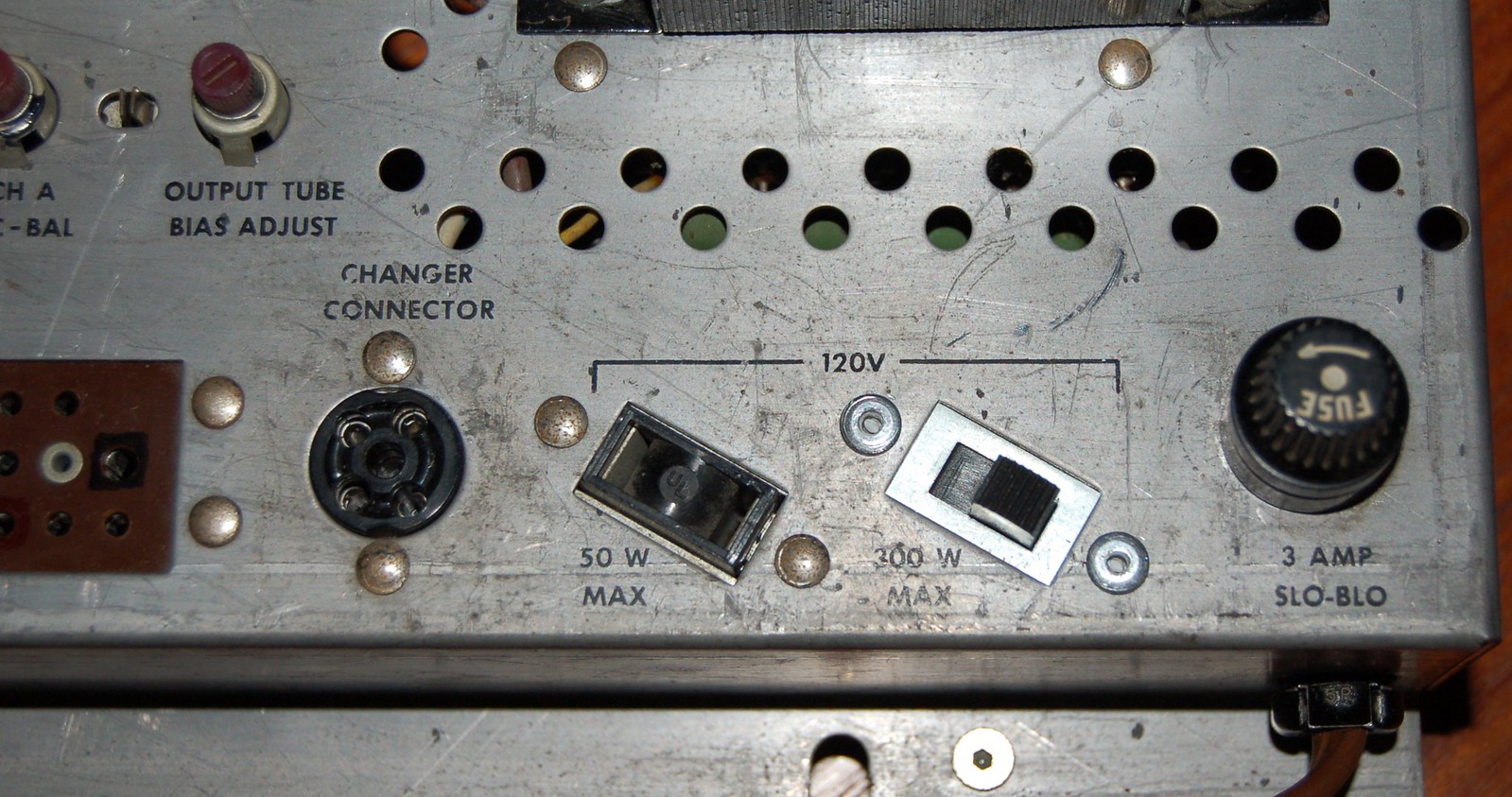
Perhaps the most trivial, but IMHO, perhaps most elegant solution. I found that a standard sliding switch available at a local surplus hut was a perfect fit (screw spacing included) to go in one of the two convenience outlet holes. No cutting required.
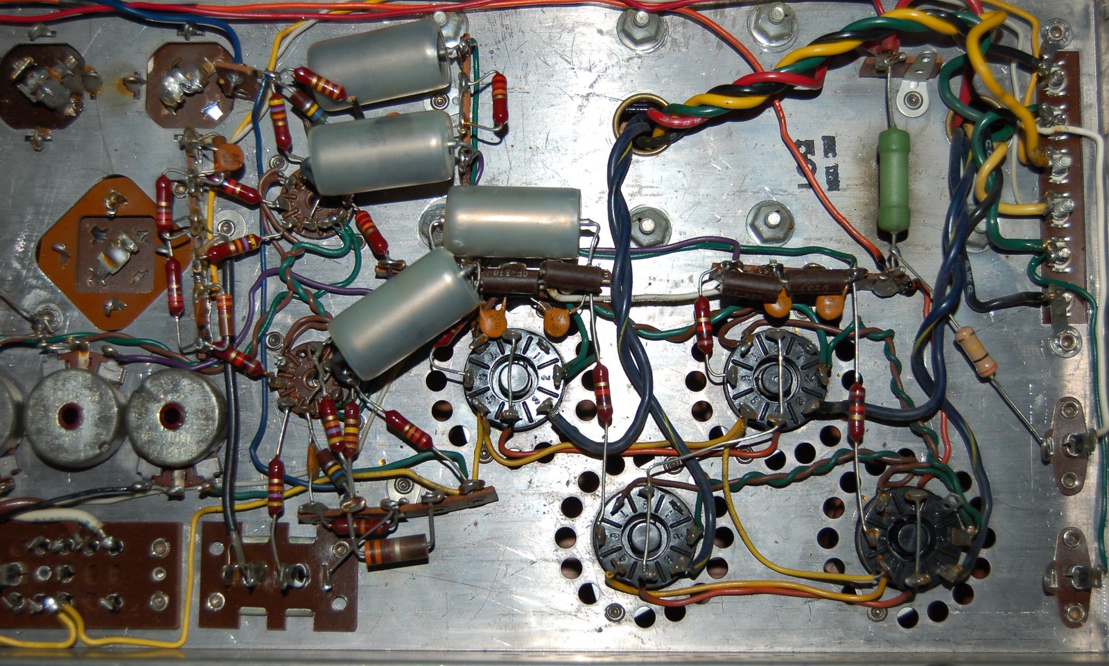
Close-up of the signal section. Grid resistors have been replaced with 220k/3W IRC GS3 and the coupling capacitors have been replaced with 0.1uF / 630V K40Y-9 PIO. The resistor to the right that's connected at an angle is a drain resistor for the power supply.
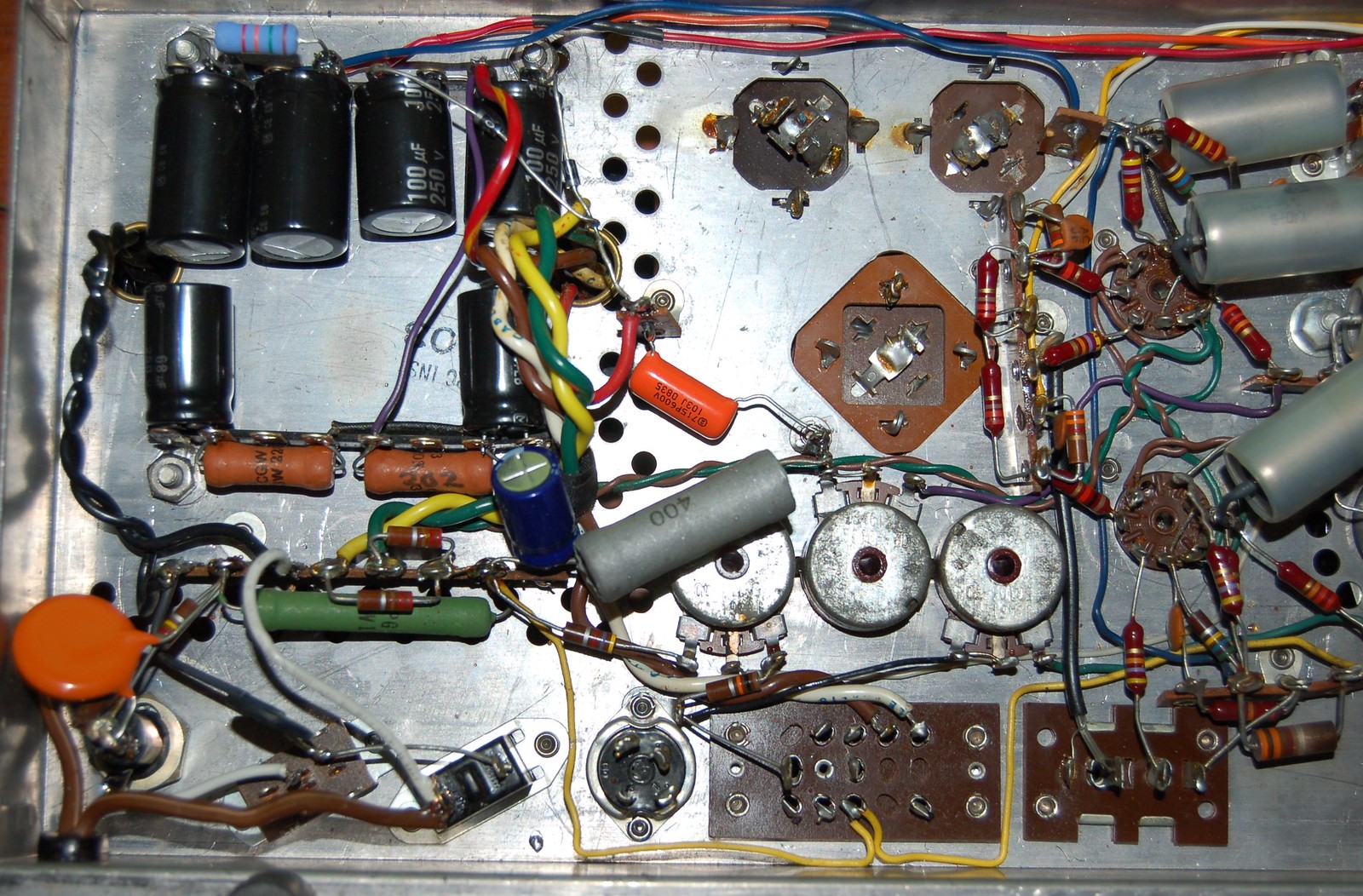
Close-up of the power supply section. The original can caps were dried out, so I replaced them with individual Panasonic electrolytics of the same value mounted on terminal strips (which fit the spacing of the power transformer screws perfectly). I kept the two 220 ohm resistors and 60uF capacitors, even though they did not connect to a preamp downstream. The original top-hat rectifiers were replaced by a pair of UF4007s and a CL80 and proper X1/Y2 cap were added to the hot side of the line cord. Given that the original bias in the amplifier used the heater string for the four 12AX7s in the preamp, a power resistor of the appropriate value needed to be added to the circuit. A 400 ohm / 20W resistor was added (and the 100uf/100V cap in parallel was replaced), and the resistor between the voltage doubler and the second cap in the R/C network was increased from 2.2k ohm to 15k ohm to get the voltages correct. While the layout isn't as neat as what came from the factory, it's still pretty clean IMHO.
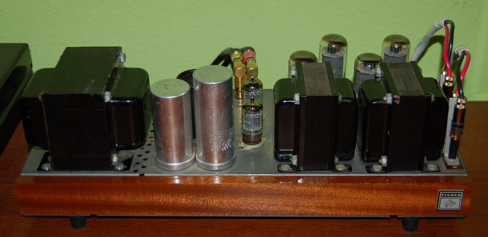
The front of the amplifier. I found a nice chunk of 1/2" thick sapele at a local woodworking shop and cut a piece to fit. I relieved a bit on the bottom to clear the screws holding on the feet and tapped and installed threaded inserts on the back side of the wood. The faceplate is secured by two 6/32 allen-head screws. Finish is a nice semi-gloss oil-based polyurethane which really brings out the grain of the sapele. I added an old Fisher badge to the front with permanent double-sided tape. I'm debating whether or not to add a power indicator light to the front (either in the center or on the left side of the panel) - I have a nice orange LED circuit that I can run directly off the spare heater voltage (has the appropriate diode and resistor), but I'm not sure if I want to risk spoiling the clean lines.
This amp sound fantastic in my system on all flavors of music (classical, bebop, rock, punk, R&B, hip-hop, etc.) and is actually leading me to sell my beloved 800C.
A big thank you to Larry and Dave for helping me get the voltages sans preamp nailed down in the power supply. My debt to these guys is ever-increasing! :thmbsp:
-D
The top remains more-or-less stock. I added my favorite Pomona screw-in banana jacks to the speaker terminal strip, but the spacing was a little closer than desired. The solution was fishpaper (dielectric paper) strips cut, punched and glued then secured by the Pomona jacks. Also note the bias test points (red & black) on the wafer connector and the slide power switch. Tubes are original Fisher 7591 and Telefunken 12AX7 smooth-plates.
Perhaps the most trivial, but IMHO, perhaps most elegant solution. I found that a standard sliding switch available at a local surplus hut was a perfect fit (screw spacing included) to go in one of the two convenience outlet holes. No cutting required.
Close-up of the signal section. Grid resistors have been replaced with 220k/3W IRC GS3 and the coupling capacitors have been replaced with 0.1uF / 630V K40Y-9 PIO. The resistor to the right that's connected at an angle is a drain resistor for the power supply.
Close-up of the power supply section. The original can caps were dried out, so I replaced them with individual Panasonic electrolytics of the same value mounted on terminal strips (which fit the spacing of the power transformer screws perfectly). I kept the two 220 ohm resistors and 60uF capacitors, even though they did not connect to a preamp downstream. The original top-hat rectifiers were replaced by a pair of UF4007s and a CL80 and proper X1/Y2 cap were added to the hot side of the line cord. Given that the original bias in the amplifier used the heater string for the four 12AX7s in the preamp, a power resistor of the appropriate value needed to be added to the circuit. A 400 ohm / 20W resistor was added (and the 100uf/100V cap in parallel was replaced), and the resistor between the voltage doubler and the second cap in the R/C network was increased from 2.2k ohm to 15k ohm to get the voltages correct. While the layout isn't as neat as what came from the factory, it's still pretty clean IMHO.
The front of the amplifier. I found a nice chunk of 1/2" thick sapele at a local woodworking shop and cut a piece to fit. I relieved a bit on the bottom to clear the screws holding on the feet and tapped and installed threaded inserts on the back side of the wood. The faceplate is secured by two 6/32 allen-head screws. Finish is a nice semi-gloss oil-based polyurethane which really brings out the grain of the sapele. I added an old Fisher badge to the front with permanent double-sided tape. I'm debating whether or not to add a power indicator light to the front (either in the center or on the left side of the panel) - I have a nice orange LED circuit that I can run directly off the spare heater voltage (has the appropriate diode and resistor), but I'm not sure if I want to risk spoiling the clean lines.
This amp sound fantastic in my system on all flavors of music (classical, bebop, rock, punk, R&B, hip-hop, etc.) and is actually leading me to sell my beloved 800C.
A big thank you to Larry and Dave for helping me get the voltages sans preamp nailed down in the power supply. My debt to these guys is ever-increasing! :thmbsp:
-D
Last edited: