

Novice repairing an SX 1080 In Protection Mode *Pictures
As the title states, I am a novice attempting to repair this SX1080. Big mistake already?
I have been searching a lot of the previous threads about the common SX units going into protection mode and thought that I could come to the understanding of my problem by seeing others problems/solutions.
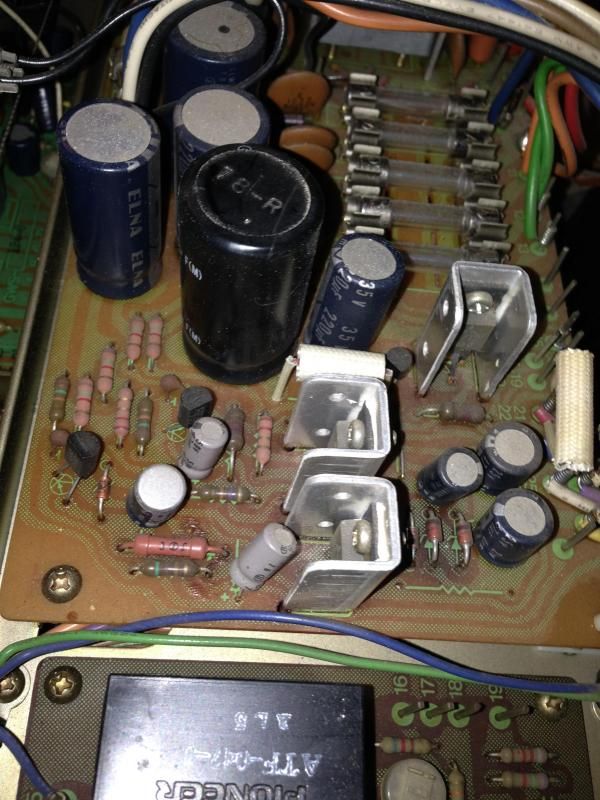
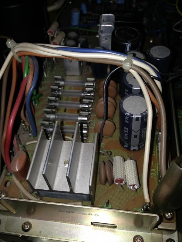
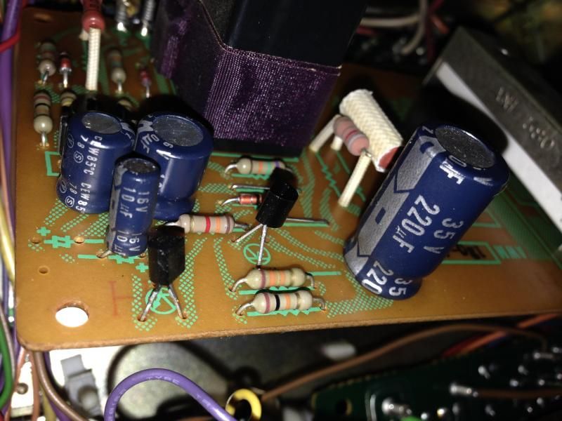
Unfortunately I am unable to really figure out what is going on with my Sx 1080 to determining the issue/s. I am initially thinking it's the Q8 and Q1 replacement on the below boards, but I'm not entirely sure since the readings don't look off to me. Could this be the thermal switch issue as well? I am am totally new to ripping into electronics and was hesitant to do so for fear of making things worse (just like I did when I was 15 my dad passed his 1080 on to me). But since I have seen others with success I figured I'd give it a go.
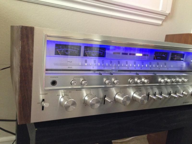
I have recently purchased this beauty a few months ago and have wanted to recreate the same receiver and speaker setup I had 25 years ago (just like dad gave me.) Fast forward to a few months ago and this newest rig was working fine except for a few pots that needed cleaning, bulbs replacing. I managed up the courage to deox a few things to get it back to sounding good and staying on the selected input. Blue LED's were added for effect.
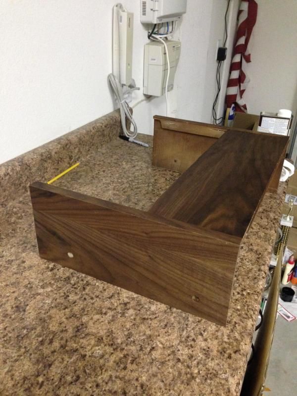
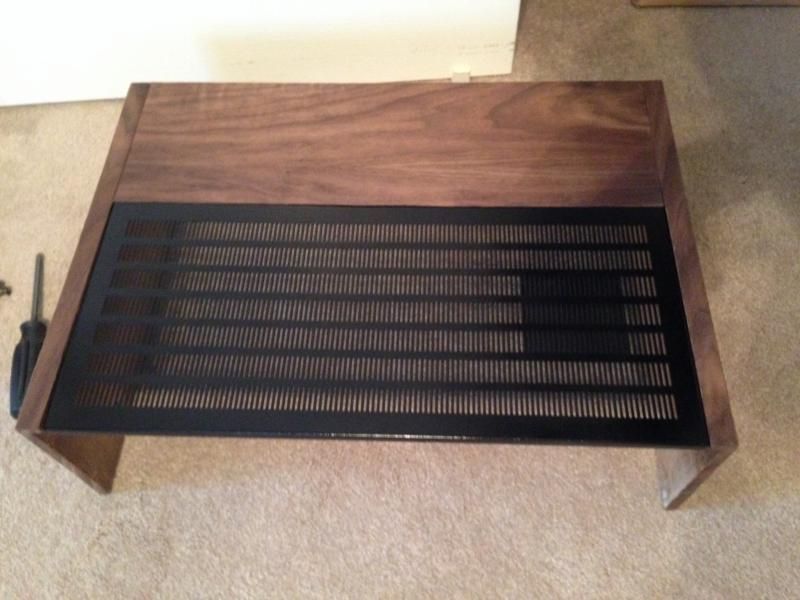
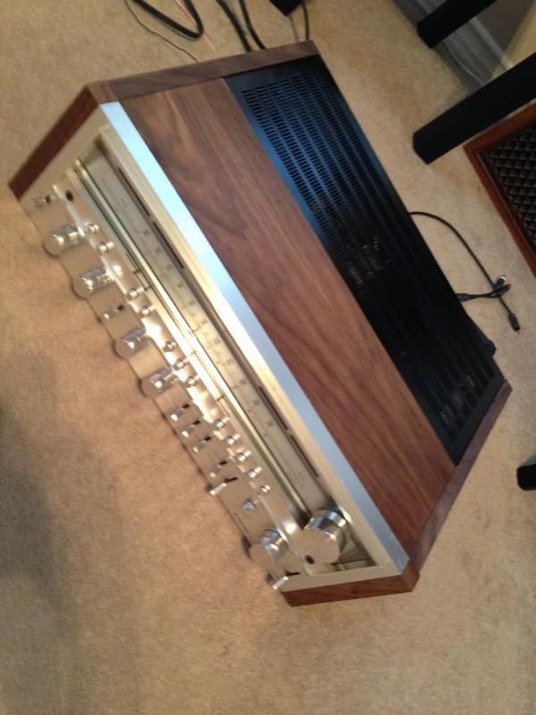
Fast forward a few more weeks and I decided to refinish the bonnet.
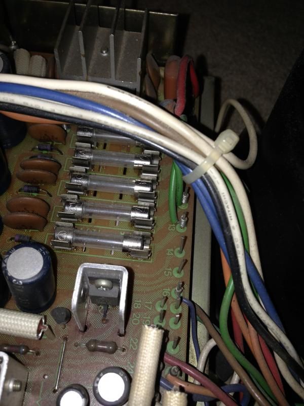
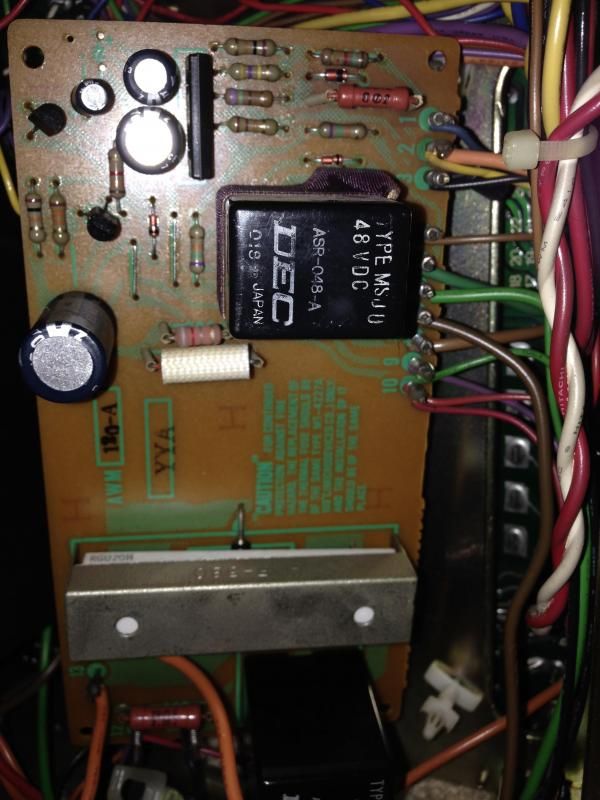
Onto my latest issue....at the initial power up after the bonnet freshen up, the unit was going in and out of protection mode for 5 minutes, then is stayed in protection mode; NO sound. I checked for the usual shorts of speaker wires, fuses, but came up empty handed. It has since not gone out of protection mode and i have began the task of testing the various inputs. I managed to figure out how to take readings with the DMM w/o making anything worse (miracle). I was not sure how to take readings of the PA3004 IC. Do I test each prong? not sure what to do next?
Readings below.
awr-152
pin 22 +60v *+65.2v*
pin 23 +23v *+25.4v*
pin 29 -13v *went back and forth -17v to -35v*
pin 25 -23v *-23.8v*
pin 27 -60v *-64.8v*
pin 16 +13v *+13.93v*
pin 19 +76v *+80.3v*
awm-120
pin 5 0.000v *0.0v*
pin 8 0.000v *0.0v*
pin 2 -60v *-64.6v*
pin 3 21v AC - Wasn't able to make this reading (i believe it's an AC reading per the other threads)
pin 9 +13v *+13.7v*
pin 10 +76v *+80.7v*
pin 4 +12v or so. *12.4v*
As the title states, I am a novice attempting to repair this SX1080. Big mistake already?
I have been searching a lot of the previous threads about the common SX units going into protection mode and thought that I could come to the understanding of my problem by seeing others problems/solutions.
Unfortunately I am unable to really figure out what is going on with my Sx 1080 to determining the issue/s. I am initially thinking it's the Q8 and Q1 replacement on the below boards, but I'm not entirely sure since the readings don't look off to me. Could this be the thermal switch issue as well? I am am totally new to ripping into electronics and was hesitant to do so for fear of making things worse (just like I did when I was 15 my dad passed his 1080 on to me). But since I have seen others with success I figured I'd give it a go.
I have recently purchased this beauty a few months ago and have wanted to recreate the same receiver and speaker setup I had 25 years ago (just like dad gave me.) Fast forward to a few months ago and this newest rig was working fine except for a few pots that needed cleaning, bulbs replacing. I managed up the courage to deox a few things to get it back to sounding good and staying on the selected input. Blue LED's were added for effect.

Fast forward a few more weeks and I decided to refinish the bonnet.


Onto my latest issue....at the initial power up after the bonnet freshen up, the unit was going in and out of protection mode for 5 minutes, then is stayed in protection mode; NO sound. I checked for the usual shorts of speaker wires, fuses, but came up empty handed. It has since not gone out of protection mode and i have began the task of testing the various inputs. I managed to figure out how to take readings with the DMM w/o making anything worse (miracle). I was not sure how to take readings of the PA3004 IC. Do I test each prong? not sure what to do next?


Readings below.
awr-152
pin 22 +60v *+65.2v*
pin 23 +23v *+25.4v*
pin 29 -13v *went back and forth -17v to -35v*
pin 25 -23v *-23.8v*
pin 27 -60v *-64.8v*
pin 16 +13v *+13.93v*
pin 19 +76v *+80.3v*
awm-120
pin 5 0.000v *0.0v*
pin 8 0.000v *0.0v*
pin 2 -60v *-64.6v*
pin 3 21v AC - Wasn't able to make this reading (i believe it's an AC reading per the other threads)
pin 9 +13v *+13.7v*
pin 10 +76v *+80.7v*
pin 4 +12v or so. *12.4v*
Last edited: