

seaneee
Active Member
Working on a Marantz cassette deck with two VU meters.
One was dead, the other worked fine (after flushing the switches and pots). The dead one was dead — broken spring.
I was able to find a replacement meter and get it installed. It works perfectly, but now the meter that worked before doesn't respond!
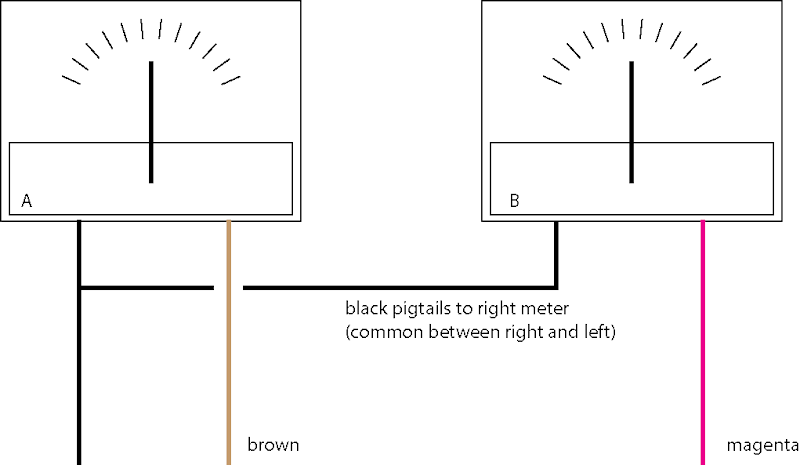
I used a jumper to connect the brown wire (see below) to the magenta and it worked. But with that connection it's just mirroring the left channel. So this tells me it's something with the wiring and not the meter, correct?
Also note, the black wire is common, so to rule out a bad connection, I used a jumper to connect the two meters and it didn't change anything.
What I don't get is how the right side could work, then the left side is fixed and the right no longer works.
Here's a little sketch of how it's wired. Be gentle, I'm considering this a learning project...
The deck in question is a Marantz/Superscope CD 304. This is a tabletop unit, not a field recorder.
Any help would be amazing. Thank you.
One was dead, the other worked fine (after flushing the switches and pots). The dead one was dead — broken spring.
I was able to find a replacement meter and get it installed. It works perfectly, but now the meter that worked before doesn't respond!
I used a jumper to connect the brown wire (see below) to the magenta and it worked. But with that connection it's just mirroring the left channel. So this tells me it's something with the wiring and not the meter, correct?
Also note, the black wire is common, so to rule out a bad connection, I used a jumper to connect the two meters and it didn't change anything.
What I don't get is how the right side could work, then the left side is fixed and the right no longer works.
Here's a little sketch of how it's wired. Be gentle, I'm considering this a learning project...
The deck in question is a Marantz/Superscope CD 304. This is a tabletop unit, not a field recorder.
Any help would be amazing. Thank you.