A re-build of my "bucket list" McIntosh preamp (C11/C22)

DC

"Manhattan Boy"
Subscriber
I've always had a thing for McIntosh and I've wanted a C22 preamp for some time now. (Hey, who hasn't? :D)

Much has been ballyhooed about the MX-110 (especially "Z" series) as being the poor-man's C22, but the circuit topography is not at all the same and all the extra tuner circuitry is superfluous to my desires. Besides, I think the real beauty of the MX-110 sound is partly due to the 6D10 compactron that is in the signal path (see Steve Hoffman thread: http://forums.stevehoffman.tv/threa...-surprised-me-today-follow-up-post-61.268103/). This is all fine and good, and the MX-110s I have heard have sounded great, but an MX-110 is not a C22.

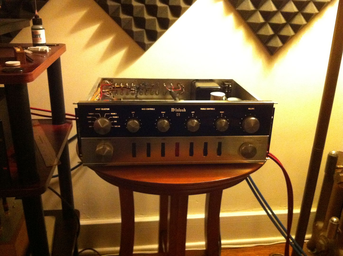
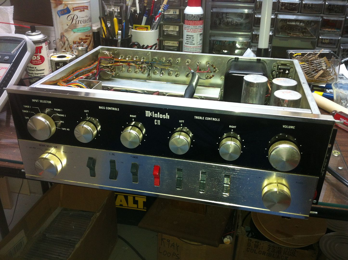
However, the C11 is. The C11 went into production in 1961 and in 1963 was given a front-panel upgrade while the rest remained virtually unchanged, and thus the C22 was born. So, last week I brought home a real "poor-man's C22" from a local seller. Save for some missing lettering on the front panel, it is spotlessly clean and included six Telefunken long-plate 12AX7s. (This is not an insignificant detail.)

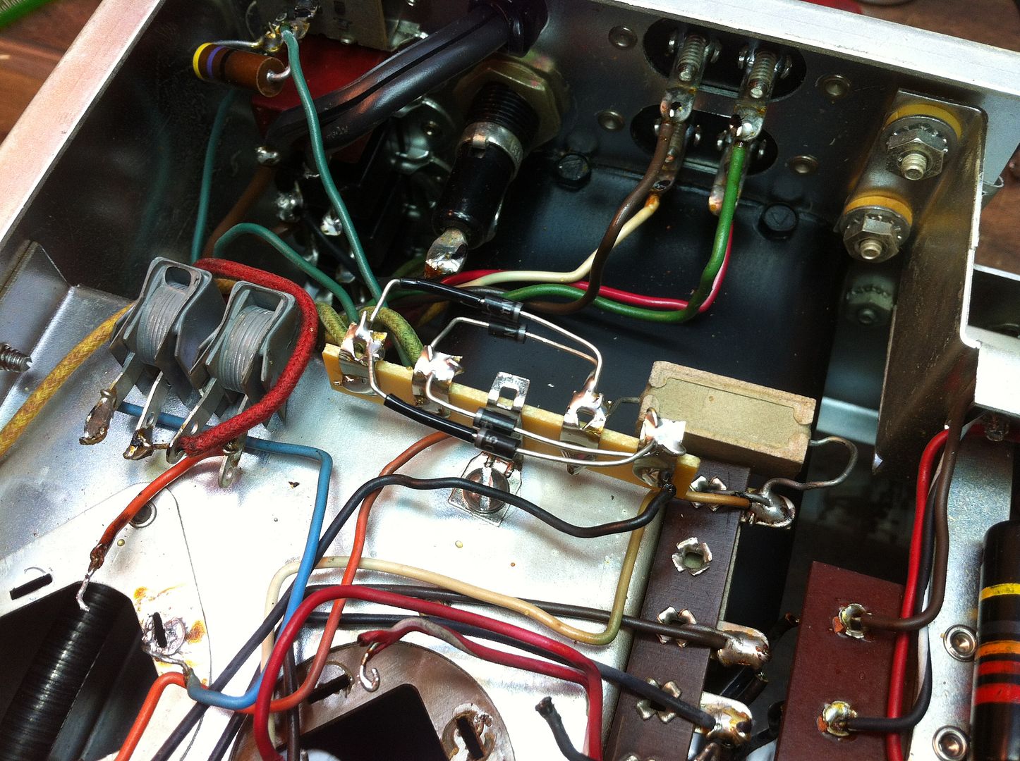
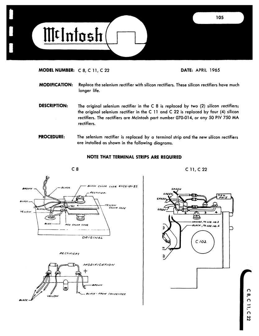
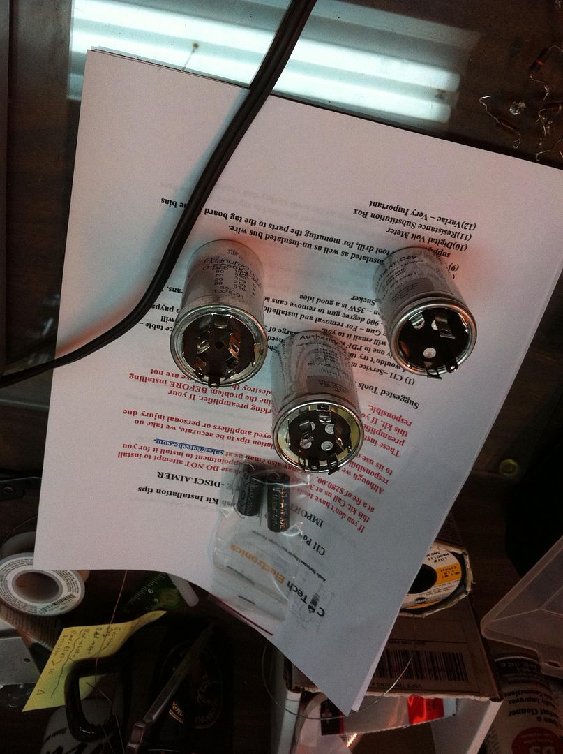
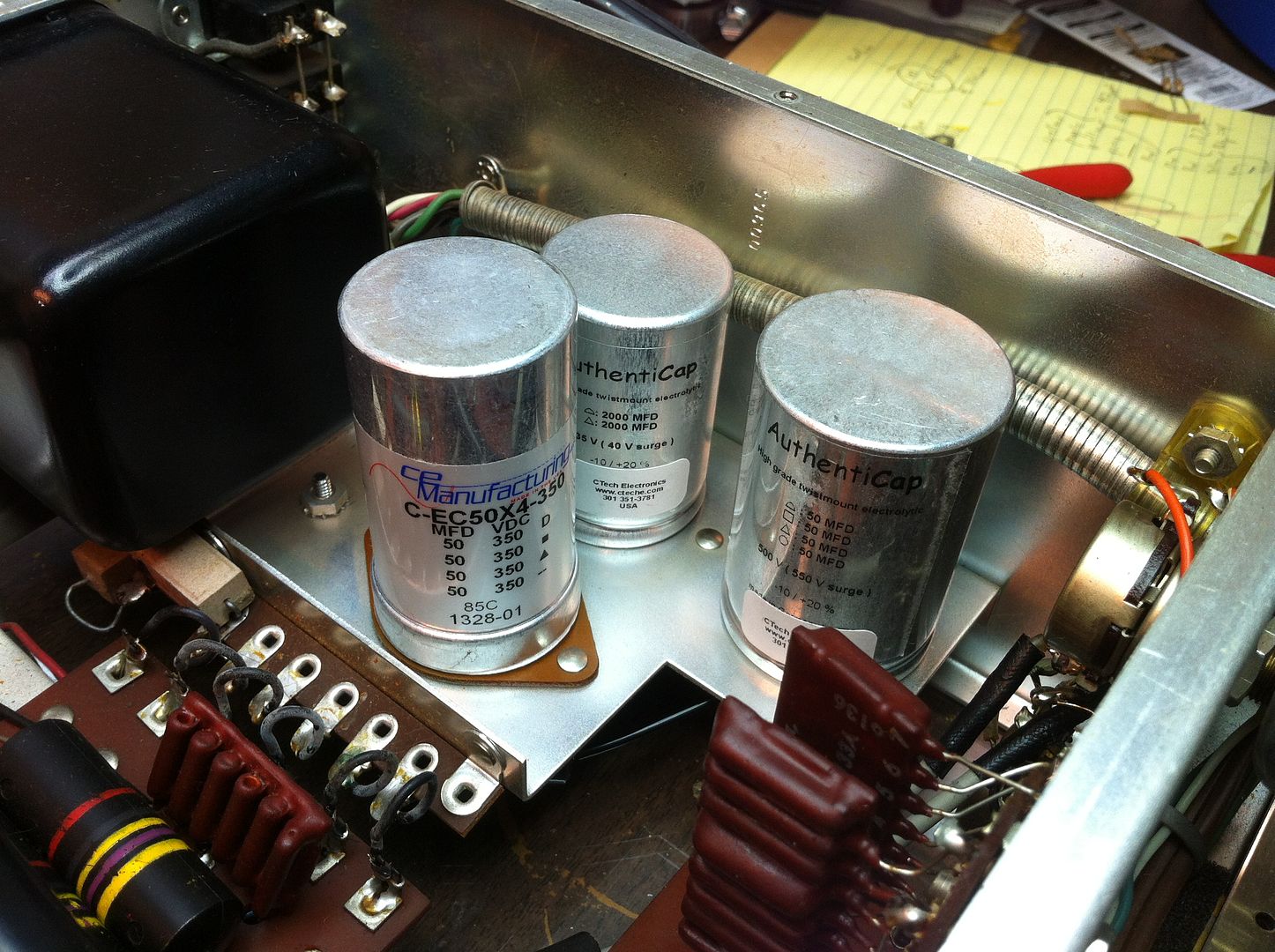
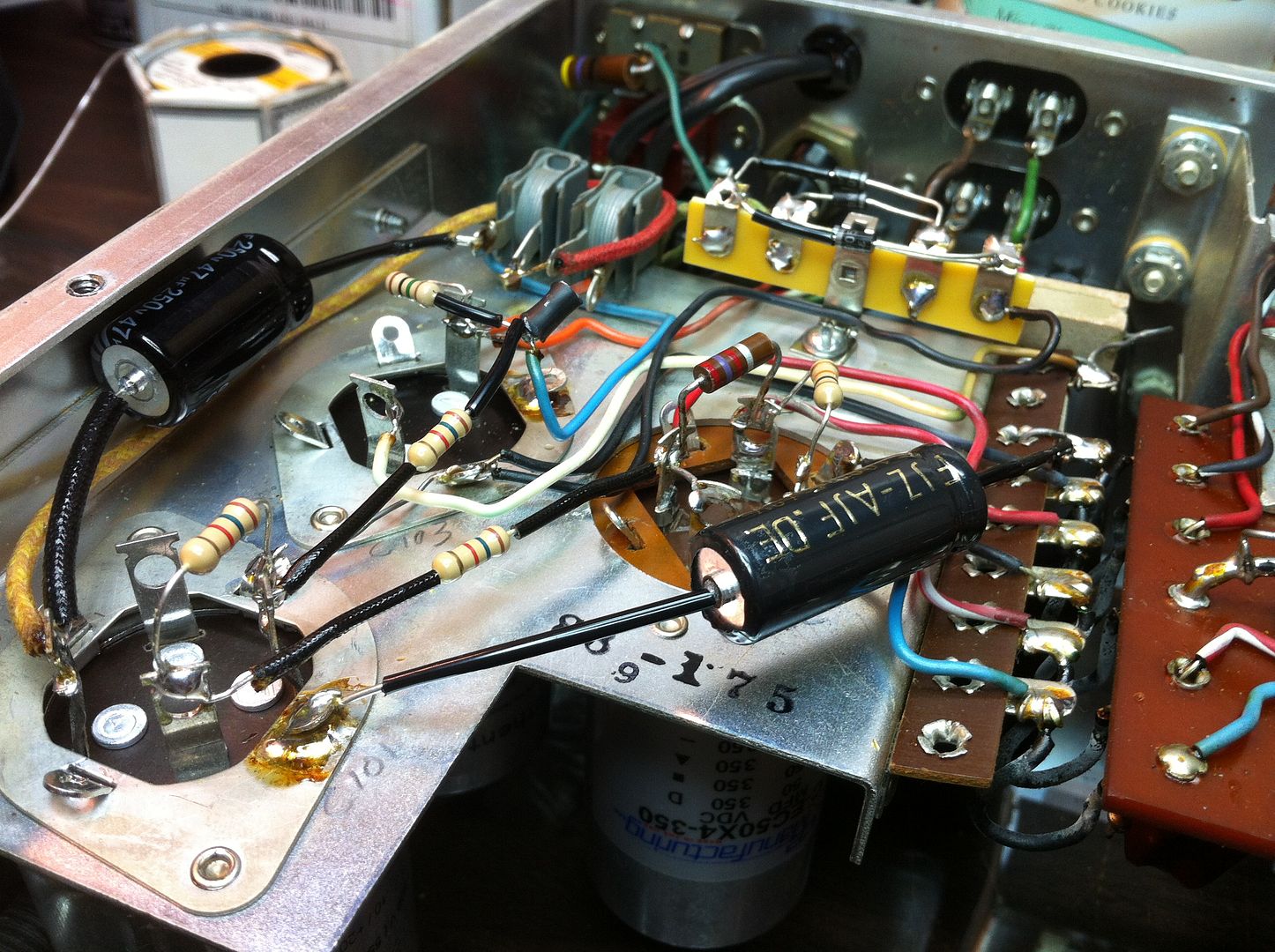
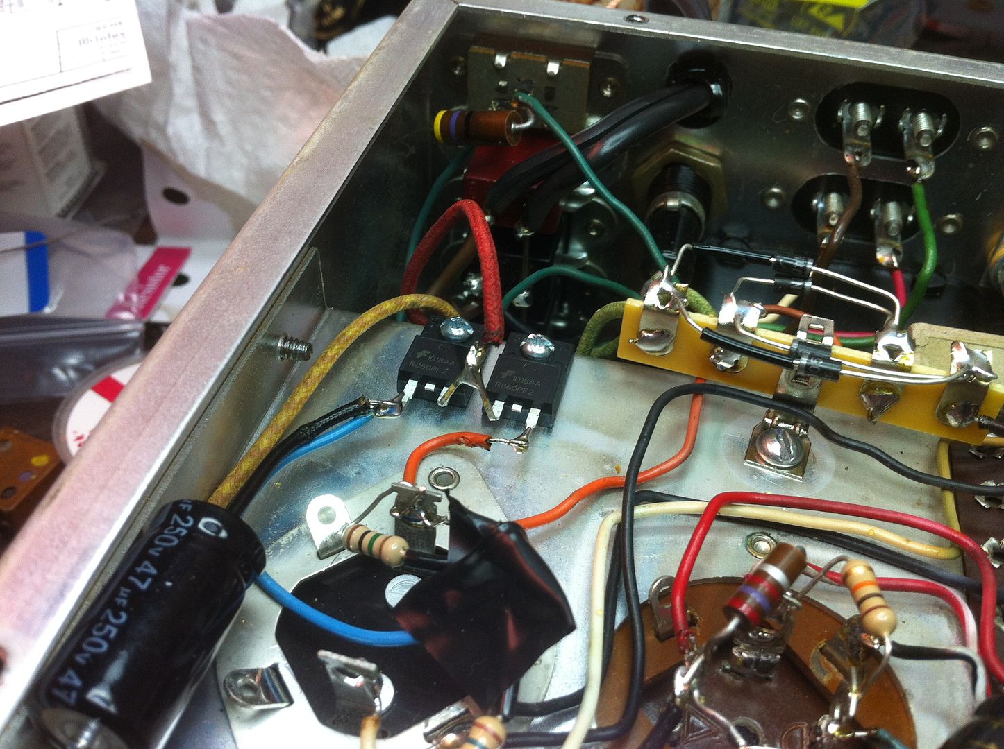
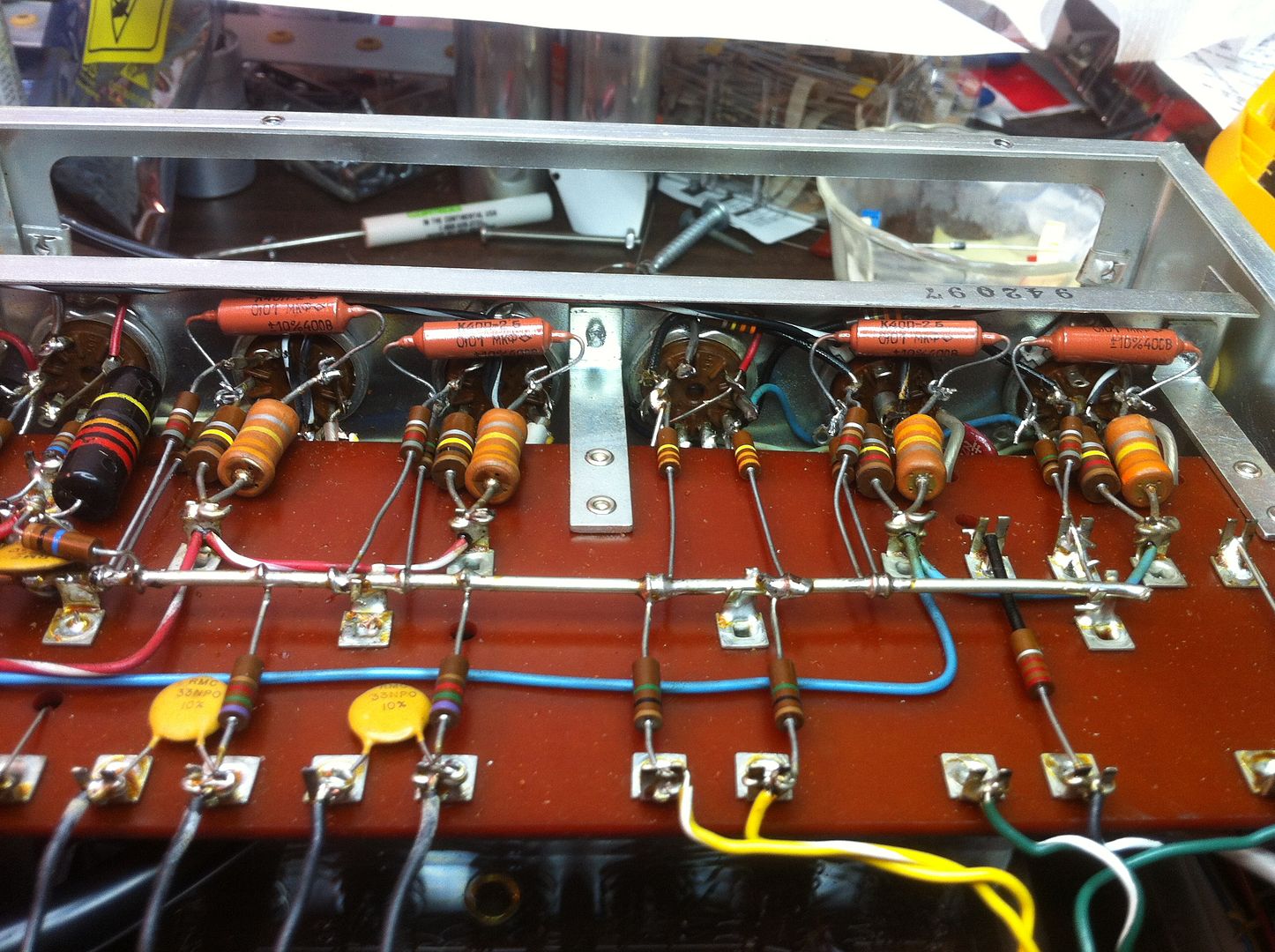
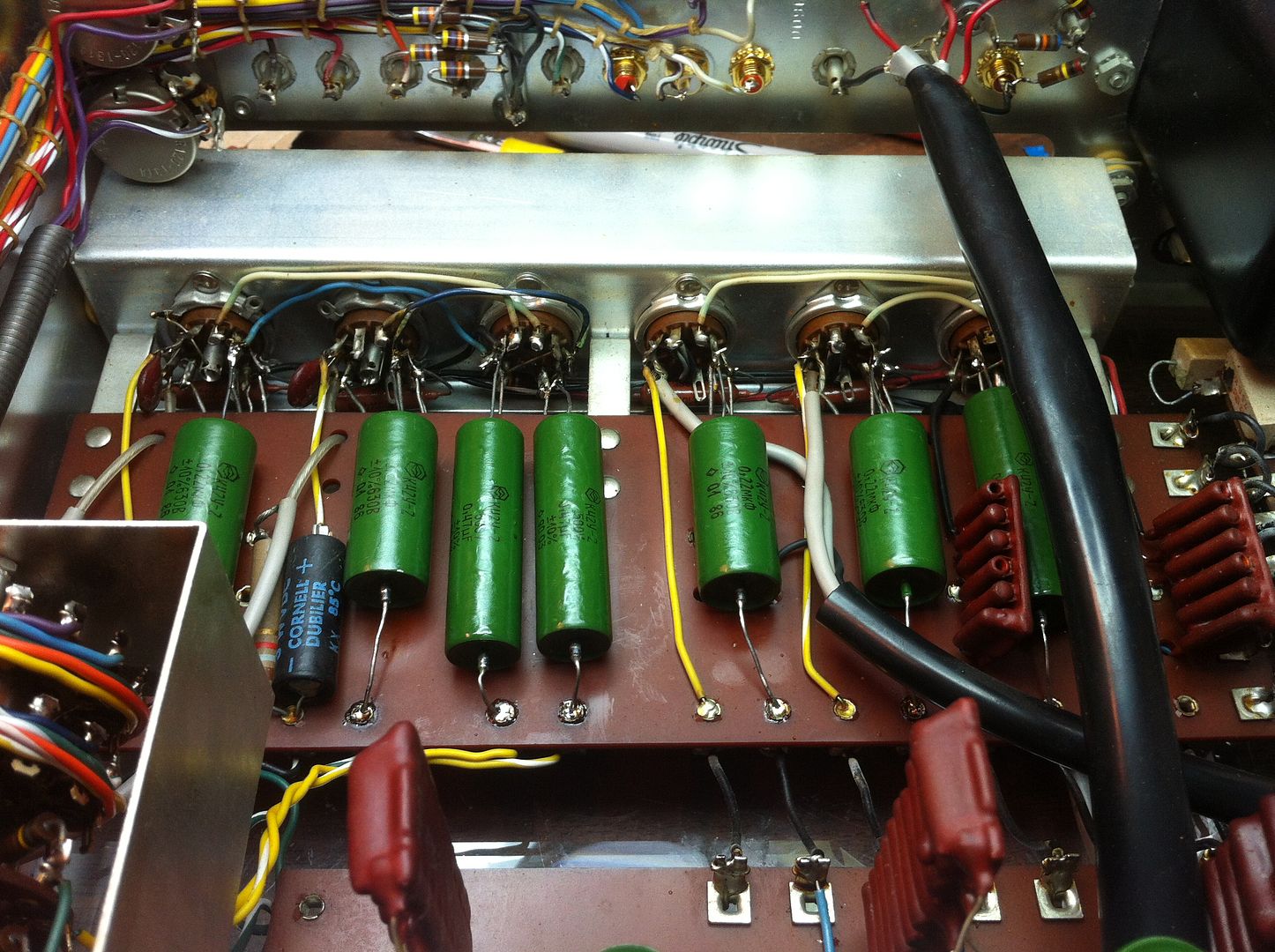
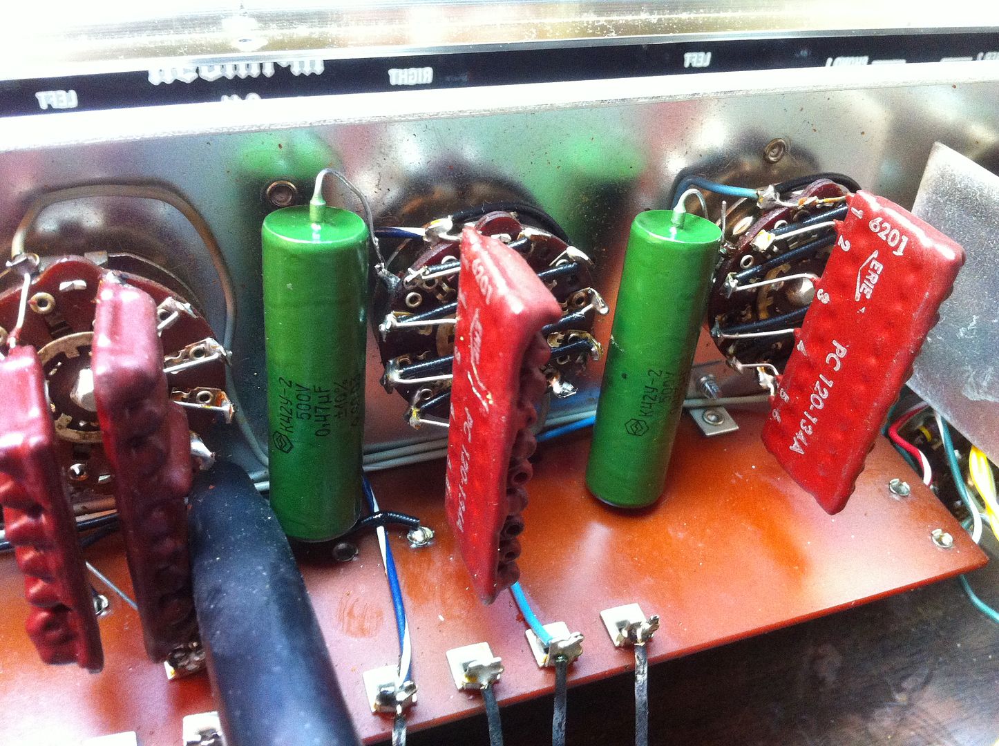
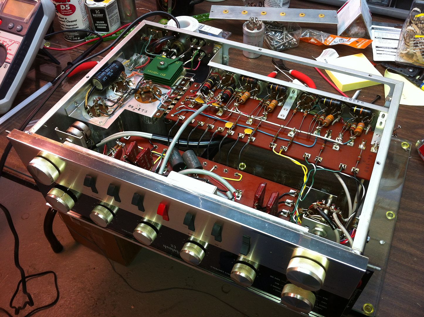
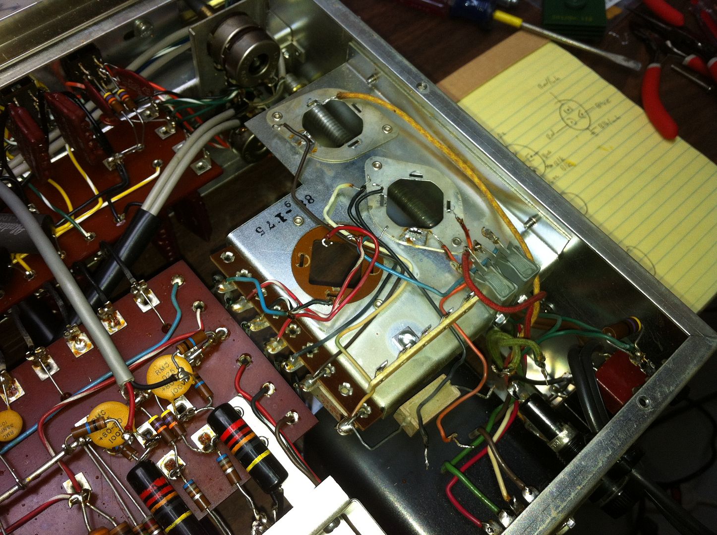
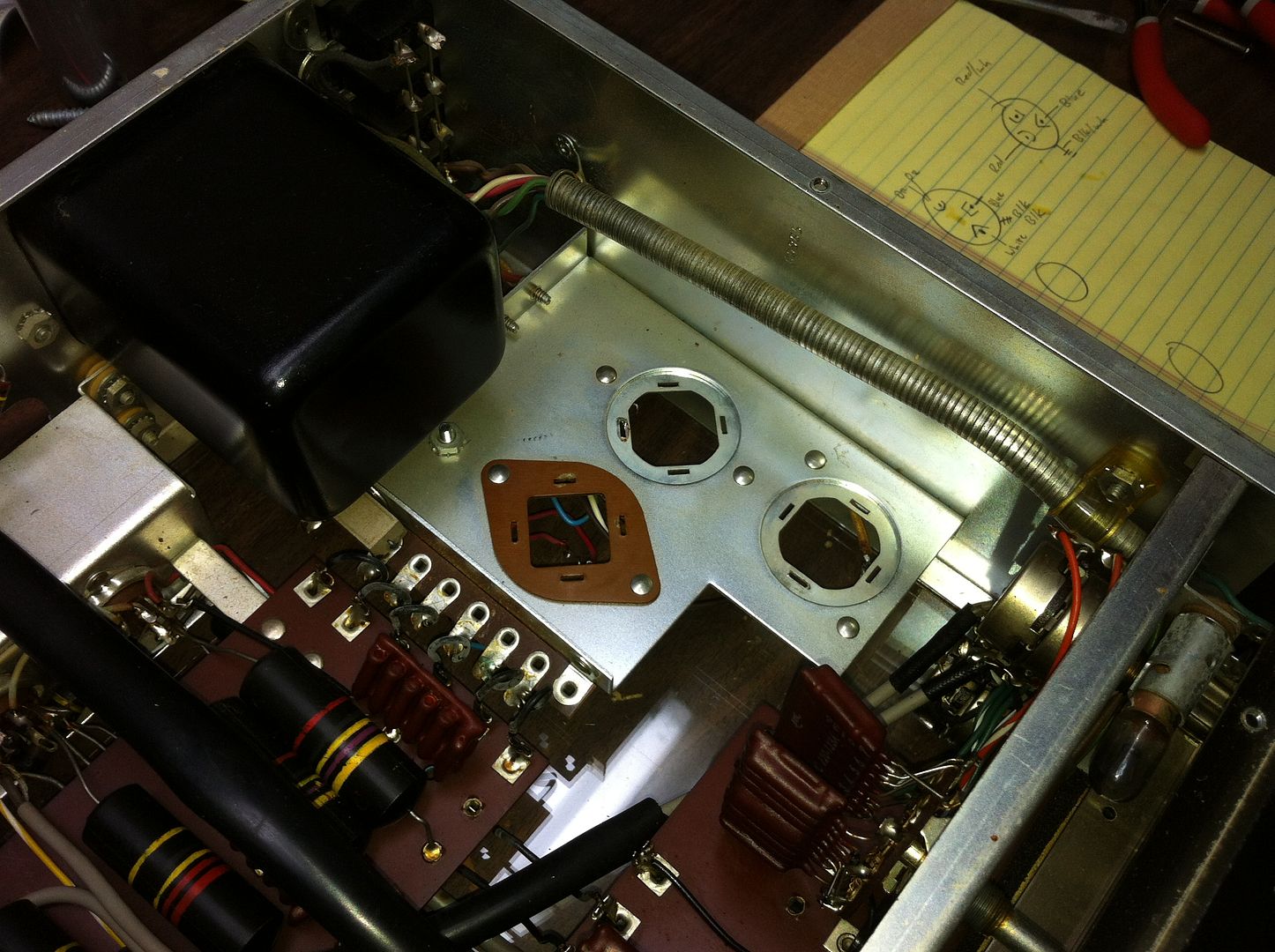
Tonight I stripped out the original can capacitors and selenium rectifier in preparation of new parts to arrive this week. Once the power supply is rebuilt, I'll give it a listen for comparison and start in on signal-path capacitors for the next step. Craig Otsby of NOSValves has some photos on his website of a C22 he repaired for a customer so I've got a few ideas of what to do next.

Isn't this fun? :music:

IMG_3486_zps7a36b530.jpg


IMG_3489_zpsfaf4ef8f.jpg


IMG_3500_zps8477401a.jpg


IMG_3501_zps293222ee.jpg
 
Last edited by a moderator:
A friend as a C-11 with a pair of MC60's driving Altec 15" co-axs and he is in tube heaven. If you really want the original tube sound this combo is the answer.
 
I was hoping the power supply components would arrive today, but they seem to have been delayed in shipping. (Maybe tomorrow?)

So I spent some time today ordering Russian paper-in-oil replacement coupling caps (based on Craig's recommendation) in the hopes that they will arrive from Russia before Spring Break!

We really need a little soldering-iron-themed smiley emoticon thingy! :D
 
I had the parts on hand to rebuild the Selenium full-wave bridge rectifier with 1N4005 diodes, so I did that much. I simply replicated the modification detailed in the April/1965 service bulletin (see below) concerning probable failures of these devices.

Anybody know the value/specs. of the two old diodes to the left? Word is (I read it on the internet!) that they don't fail slowly and reduce voltage like the Selenium device; they either work or they don't. These do (or at least they did), but I'd like to be able to replace them anyway.

IMG_3505_zps5b3692e1.jpg


C11_service_bulletin_zps3f6ca631.jpg
 
Progress tonight:

1. The capacitor kit arrived and is installed. (No more hum! DEAD quiet, in fact, as it should be.) Several values in this kit are higher than the originals, so there is plenty of extra PS capacitance to go around.

2. The B+ rectifier output indeed is low. With 117VAC on the variac, measured voltages are down from spec. very similar to what Craig found in the C22 he rebuilt. (I realize now that I misread his assertion that these devices either work or don't. He was referring to replacement silicon components, not these old things. Doh!) So yes, these need to be replaced.

This is what $219 (delivered) gets you - nice!
IMG_3507_zps15d38b65.jpg


From topside, they are very handsome:
IMG_3514_zpsf7cedce4.jpg


Underneath (I think I'll tidy this up and install a "junction point" to solve the current floating heat-shrink mess):
IMG_3516_zpsc50a47f6.jpg


Temporarily up in the library playing Beethoven:
IMG_3521_zps5dab3d1b.jpg
 
Not much, yet. I only got a short time to listen on Thursday, and Friday "Happy Hour" yesterday turned in to "Happy Entire Evening" (not that I'm complaining :D), so no listening.

On Thursday, I did notice that the volume/balance was uneven, so I trimmed it with the side volume trimmers. I figure it could be old caps. in the signal path, uneven tube values, or dirty contacts. I ordered a couple of tiny tube contact cleaning brushes to get them clean and will rotate the tubes around a bit. My tube tester is not working right, so it's not easy to test them yet for conductance/balance.

Once I get new caps in and all that figured I'll see if I can determine if it's a volume pot tracking problem, imbalance with the trimmer pots (I'm actually interested in bypassing those later if the balance holds true), or something else. All in due time ...
 
Today I replaced some of the rear-panel RCA connectors with some inexpensive gold ones I had laying around - much tighter fit.

After a bit of listening, the right channel became weak and distorted. I did a little bit of troubleshooting and it seemed to be possibly related to the tube that was in the final position. I think either the contacts are getting dirty after heat-up or some bad caps are wreaking havoc on the circuit. No funny aromas, so I don't think a resistor (for instance) was overheating too much, and no obvious red-plating that I could see.

Ah well, time for it to sit patiently while the new components come. Maybe I'll try to get my tube tester revived in the meantime ...
 
Baby steps ...

B+ diodes replaced with Fairchild components:
IMG_3534_zps72812a80.jpg


I received the .01uF Russian POI capacitors, so I got them in place last night. Wow, what a colossal P.I.T.A. location to work on desoldering old components! I am hoping the other values show up this week so I can at least get somewhat operational for the SMAC meet here next weekend:
IMG_3535_zpsf4e010b5.jpg


I haven't powered it up and tested voltages, yet. I'll probably wait until all of the coupling capacitors arrive and are installed.
 
Progress!

I picked up another international package today at the Post Office from The Motherland, so we are now sporting ten new Russian paper-in-oil capacitors to accompany the four previously installed a few days ago. (Yay!) Using a cheapy digital LCR meter, I checked a few of the old ones I pulled out and several were way out of spec. This (and probably age-related general deterioration) might explain the rolled-off, closed-in sound I was getting as well as the output imbalance and the eventual right-channel distortion.

Now? Now the sound seems ... oh the sound. :music:

I do think there is some merit to capacitor break-in (and the time and signal presence required), but right away I am hearing a WIDE OPEN and SPACIOUS soundstage, that which was sorely lacking before the component upgrades, as well as appropriate high-frequency extension. Nice! (Remember, I'm using an Audio Research SP-9 Mk.III as a reference, which has extension-a-plenty and all the other fun superlatives, so it's a pretty high bar.) I'll plan to leave a CD going tonight on auto-repeat to keep some signal present in an effort to get these things to wake up a little faster.

While under the hood, I did some spot checking of resistor values and nothing seemed too out of the ordinary. I've not decided for myself about the merits of a full re-resistor yet, though I won't rule it out as a possible rainy day project sometime in the future.

I also checked the voltages against the McIntosh schematic. With exactly 117vac on the variac, I measure:
- 309v, should be 310v
- 293v, should be 290v
- 265v, should be 268v

Happy? Youbetcha!

Unfortunately, the filament voltage is a bit high (20.8vdc/3=6.9v each), which is bothersome. I've got it plugged into a bucking transformer which steps the line voltage down a bit more to keep things in check for the time being. I'll need to pad down the filament PS a little bit, I think. (I've read that this sometimes can be a problem ... )

IMG_3537_zps302a763f.jpg


IMG_3539_zpseb4b5985.jpg
 
Great effort. You've done some great work and the pictures have been very clean and detailed. It's been fun to follow your project.
 
Thanks for the kind words, gang!

I did some more listening last night (no school today = up late!) and I think it continued to smooth out a bit. Overall, the noise floor seems very quiet and the music seems to be portrayed with confidence, strong controlled bass, beautiful midrange bloom (not the right word, but that's what I've got at the moment), and smooth detailed highs with lots of air and space.

Last weekend I got my tube tester somewhat working too (using a couple of known tubes as a calibration reference) so I was able to test the old Telefunkens. All but one were strong (one very weak) and most balanced pretty well. So last night I put a couple of special matched Sylvania 12AX7WA tubes in the phono stage and carefully selected the locations for the four remaining Teles for balance. Sounds good!
 
It looks really nice Don. I sure wish I could hear it. Enjoy the fruits of your labor.
 
Awesome effort, it really tickles my interest in tube gear when I see threads like this......:thmbsp:

You've done a great job, I'll bet you'll get a lot of enjoyment out of it.....:music:
 
Shameless bump ... this thing sounds quite nice! I've got a few more components still to replace (some misc. caps. related to the phono stage, which sounds like it could still use a little more help) and I'm contemplating ordering some much nicer RCA connectors to re-do the whole back panel.

I recently had an issue with a bad tube in one channel (microphonic to the point of squealing/whistling) so I found a suitable substitute among the Dynaco-branded Telefunkens pulled from my PAS-2 (cryo'ed JJs in that one now) that matched well on the tube tester.

It's nice to have a McIntosh preamp back in the system full time again. :thmbsp:
 
If you will read David Obrien's white paper about his years at McIntosh I think there is mention of the fact that the resistors in the phono circuit were the limiting factor. They were inherently noisy and should be replaced. If not there it will be in an article about the reissue C-22.
 
Back
Top Bottom