Stumbled on this by accident but figured it was worth piping up as I've had several 3233 units with current one extensively modded. From the pics above, the 3233 is similar to the 3235 AND 3222 at minimum. All 3 share the same amp board layout.
Anyways, the DC offset is NOT adjustable for these. The 2 pots on the amp board are for bias. Don't touch them less you want to destroy the outputs. The heat sink is extremely weak and outputs will get HOT just idling if set incorrectly. Ideally, you shouldn't feel much if any heat holding hand couple inches above amp board. If you know how to bias boards, google the outputs and search. The ones in the 3233 were used in other popular amps and are used in DIY amps as well, meaning there's enough documentation there to ballpark the bias SAFELY. Don't go crazy with the value. I have a post in another forum that covers the biasing IIRC but you'll have to find that on your own. It should have 3233 in the header but was probably for another issue like offset and biasing came up, can't remember. Either way, it's easy to bias these.
If your DC offset is incorrect by a high margin, I suggest finding the resistor(s) failing and replace them with 1% resistors, or better yet, replace all the resistors on the amp board (can leave the white log resistors alone) in one go with high-end 1% as the factory ones aren't the greatest and you'll probably find some were replaced already as they won't match others on the board, even in a left/right scenario which could theoretically cause sound variances between left/right channels. Pull a leg to a resistor to break circuit, then check resistance. If the ring colors are near impossible to decipher, find a matching resistor elsewhere in the unit and compare resistance. They used 10% or 15% tolerance in most cases, and like to drift to one end of the tolerance limit or the other when WORKING ok.
If you lift the amp board off the metal stands, be mindful NOT to loose or forget to reinstall the rubber or paper washers that isolate the PCB from the metal.
The 2 other pots on the tuner board are for the tuning strength needle and the FM Stereo detection LED sensitivity i.e. how wide of an area on the tuning needle sweep FM Stereo LED will come on. Can be tweaked slightly to increase FM Stereo detection. Needle strength can be artificially altered. If you live 5 miles from a powerful FM radio station and the needle only goes to 3 or 4 strength with great antennae, can increase to 5 so it reflects more accurately.
My 3233 is about as close to "new" as you'll get as all film and electrolytic caps were upgraded in the amp, tone, and psu boards (left tuner alone as it works good with strong FM detection and left both phono alone as I don't use them) and DC Offset was a tad higher on I think the right channel but still below the "oh no" level and left was low. It's normal to be a little off considering DC Offset is "fixed".
Also, make SURE the 3 amp channel fuses are identical. These amps are actually VERY sensitive to mismatched fuses as I believe the audio actually transmits through them. I know in my youth I'd pop the 3 amp often pushing 4 12's with loudness and bass maxed listening to early 90's rap. I'd use foil, 2 amp, 4 amp, and eventually 5 amp fuses. There was a difference in audio quality between foil and 5 amp. Also, rule out the tuner, aux, etc. 1st before assuming it's something else. Bad digital converters, bad RCA cables, failing CD players, issues with the FM/AM/AUX/Tape etc. buttons can cause channel to channel issues too.
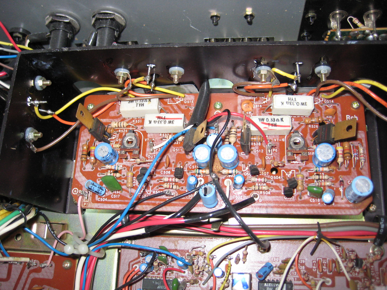
EDIT: To increase higher freq. accuracy, i.e. more accurate highs that correctly reflect the source audio w/o sounding garbled or muddy, replace the 2 green polyester caps C517 and C518 with a high quality variant. I used Vishay-Roderstein Metalized Polypropylene there and it made a huge difference with the highs. It also tightened up the bass a bit to sound less sloppy/boomy. This was AFTER all electrolytic caps were replaced that it improvement was still found replacing these 2 film caps.