• The move to the new server is done. There are some software and database maintenance updates in process. This has us passing the hat around to help out. We appreciate any donations. Seriously, even a dollar helps. The payment page may be found here - https://www.audiokarma.org/support.html

Sansui Frequently asked, and more...

Status
Not open for further replies.

Morden2004

Relaxin'
This thread is locked and can only be updated by a moderator. If you have a contribution for this thread, send a private message to @dlucy the current moderator.

The Exclusively Sansui FAQ List

Lights out in an 8080/9090? Here is a repair tip that will remove the light circuit from the selector switch which often fails.​
"With the top cover removed, looking down on the right side, there is a pc board about 4" x 5 " that the selector switch is mounted on. On that board there are connection plugs. Second from the right there is a connector with a orange, grey, black and red wire attached. There is an open location on that connector. Move the red wire(~6.5 vac) from the end position to the vacant position next to the black wire. This new position will tap into the 6.5 vac supply that the source selector uses. Now the tuning lights will be on all the time and the orange source lights will switch on and off as the function selector changes(am,fm,phono,aux,dolby fm)​

  • FAQ 12
    How do I sell my surplus gear here on AudioKarma?

    Subscribe, then use the Bartertown forum.
  • FAQ 13
    Where can I get replacement lamps for my classic Sansui?
    (Part 2)
    AudioKarma member Dave Wojo (dgwojo) has a great site for ordering bulbs. Click this link: dgwojo
    AudioKarma member Denis (dhenryp) also sells lamps for classic Sansui gear. Check out eBay member ID 'dhenryp' on eBay

    or contact either member using AudioKarma email.
  • FAQ 14
    I have heard about the problems with glue on component boards. How do I get rid of it?
    Click the link below.
    Sansui glue
  • FAQ 15: How do I tell what year my Sansui equipment was manufactured?
Easy! The serial numbers on most Sansui equipment follows a standard;​
FF Y MM ####​
where FF = a Factory Assembly Line number​
Y = last digit of the year of manufacture (you need to know the first year a unit was built - see the Sansui Database reports)​
MM = the month of build where 01 = January and 12 = December​
The remaining 3 or 4 digits are sequentially applied on the line in sequence.​
Example:​
AU-999 Serial Number is: 222010985​
Manufacturing line #: 22
Year: 1972 (first year for the AU-999 was 1969)​
Month: January
Serial component: 0985
  • FAQ 16: What does the Connected/Separated switch on my Sansui xxxx do?

    Read this excellent explanation by our very own EchoWars here .

  • FAQ 17: What is a 'Poor Mans Variac' and how do I build one?
    Read this thread for an explanation of the PMV here

  • FAQ 18: crosspoint screws in Sansui are not usually Phillips - they are JIS

  • More FAQs or useful threads on Sansui gear:
  • FAQ #19: Access to speaker relay & meter lamps on 9090/9090DB
In the thread link below, Dr*Audio explains how to access the speaker relay, and tips on replacing the meter lamps with LED's.​
 
Last edited by a moderator:
Register to hide this ad
the stv-2h and 605a are pretty much the same. they are mounted the same.

You'll have to search a bit for the 605. i would talk to electronics places that were nte dealers and see if they have a stock of them somewhere.

last time i checked consolidated electronics had the stv-2h devices.

An update on availability of the STV-2H: I tried to order some today, and the (very nice) guy at Consolidated who I talked to said he's sold hundreds - but they're all gone now!

If anyone knows where either the STV-2H or the NTE 605A can be obtained, can you let us in on it? Thanks.
 
Good Post Jordan. I finally got a chance to look at my 5000Xs. It has the F-1040-1 boards in it but the board has two sets of two diodes in series on the botton of the board, HEP 170 is printed on the four diodes, no themoral connections. The two SA485 have a heat sheild that looks homemade, a circle of sheet metal around the transisitor and strap from the circle that exttends a 1/4 inch up and then across the top. The boards have the c458 transitor.

The Question should these be changed.

Thanks
Bob
 
Sounds like a very interesting, but incorrectly done mod.

The person used two diodes in series to compensate for the fact that the original devices were dual-junction. That much he knew. However, the those types of diodes are probably not designed to change value with temperature - and that's where the problem is.

If there is no thermal feedback from those devices, then there is no way the bias gets backed off when the amp heats up. This will eventually end up in a thermal runaway condition and the output transistors will die.

The heat shield looking thing on the 2sa485 used to be the hardware that attached the original diode devices. They were epoxied to the tops of the transistors and can be difficult to get off without pulling the board and chipping the epoxy away.

The 2sc458 should be replaced. Its really a crummy transistor.

If it were me, I would pull the diode mess out and put correct devices in described in the retrofit thread.
 
Thanks for the reply. That's what I thought. The way the four diodes sets were made cripped at the series connection then soldered, each set the same, and the put in the exact same position, it looked like it came from the factory that. This one goes under my bench, the dining room table, since it is working fine except for famous 8.3v 150ma indicator light which is dead.

Thanks
Bob
 
Don't try to work on the driver boards with them installed in the chassis. its a headache and will only cause you troubles. They MUST be removed from the chassis if your repair is to be a success.
attachment.php


There are 8 leads to unsolder per board. Rail, output cap, 2 ground straps, 2 protector leads, and two input leads. Note their locations. You'll need a soldering gun to remove the ground straps.
attachment.php

attachment.php

attachment.php

attachment.php

attachment.php

attachment.php

Nice work!!
Great photos.
One question. Instead of the solder gun, why not drop the 2 capacitors next to the amplifier boards? You'll have a clear view of the solder side of the board to work on.

Ron
 
Its a little more difficult to get a tool in there to loosen the clamp. I found it easier and less time consuming to unsolder the ground rather than dropping the caps down.

Your mileage may vary.
 
Has this 5000X already been repaired?

Just picked up a pretty nice looking 5000X :banana: It has a couple of small problems (I'll get to that later!); but much to my chagrin it has two of the dreaded F-1040-1 boards.
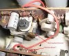
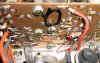
Sansui 5000X Q1.jpg

It looks like something has been done to this - can someone confirm this? )And even better, is it a Sansui-sanctioned repair?)

Sansui 5000X Q2.jpg

Thanks!!!
 
The standard Dolby "B" calibration tone is 400Hz, or at least it is on my Kenwood Eleven II and Teac AN-60 and AN-180 units.
 
About to mod the drvr boards

A friend of mine gave me a Sansui 5000A. he said it had been worked on. after opening it up, somebody had tried to repair one of the driver boards. they didn't use exact replacement transistors. the board is NOT fried. they didn't bother to attach the diodes. I'm going to do both boards. I'll post the results.
 
sounds like the diodes needed are unavailable so this mod is kaput IMO. sure would be nice to have been given alternative part numbers for them. The 5000a I have is going to die a fiery death I guess.

digikey, mouser, allied all blank for both #s
 
Last edited:
There's some local shops and stores around here that have lots of old stock, I'll check around and see what turns up.
Don't give up yet, lots of stuff out there still. It's just a PITA to find sometimes.
 
so what are the V/I characterisstics of those diodes. thyy look like plain vinnila silicon switching diodes or something close, which act as temp sensors in some cases and could maybe do the job. How much do they need to "vary" with temp? I got an "A" with the 1040 bds and need to fix it.

rather than desolder all those wires, Id just cut em and splice in a new piece when replacing. gnd straps too.
 
Last edited:
I think 2 silicon (.7V) diodes in series giving a 1.4 volt drop and some what of a change in voltage with temperature would do the job nicely. Need to mesure that voltage across those diodes. At cold and at temp.
Or a thermister with rite temp coeff and resistance.
 
This is great repair tips. I've been reading and not sure if this is cause of my main problem with my 9090DB. After cleaned contact of the vol control and other pots now sound from both channels works fine(except still have some drop out when I turn the bolby selector switch, still need to cleand more contact) but the FM does not go to stereo and I have to push the FM MUTING OFF to be able to get the sound out of FM. FM reception is my main problem at the moment and really need some help. Thanks guys.
 
Hi,I have a Sansui 5000A (bought while in Nam) now has one modified 1040 board, the other channel is original and doesn't work...I also have a 5000X that I purchased several years ago on eBay with F6013 boards but one channel is out. Can I make one good unit? Any pitfalls? Open to any and all suggestions. thanks Jim
 
MZ2361 would probably work, but one may have to compensate a little for the slightly higher vF. But I'm not sure as I haven't tried it yet.
 
More shots of the new devices mounted up and epoxied in palce:
attachment.php


Once you've made sure the epoxy has set, you can solder in the new diodes. DOUBLE CHECK TO MAKE SURE YOUR POLARITY IS CORRECT.

i am not an expert but how can i check the right polarity of the diodes?
how to do this?
 
The voltage values of the caps won't make a significant difference and would have no affect on this issue at all. If you want to pursue it, I'd recommend opening a thread in the main Sansui forum. There are much better techs that may not see it in this thread.

- Pete
 
Status
Not open for further replies.
Back
Top Bottom