• The move to the new server is done. There are some software and database maintenance updates in process. This has us passing the hat around to help out. We appreciate any donations. Seriously, even a dollar helps. The payment page may be found here - https://www.audiokarma.org/support.html

sa-232 rebuild has begun

madwing

AK Subscriber
Subscriber
i finally got all my parts from mouser, and am home sick today (seriously :sigh:, bad sore throat, flu-symptoms, etc.), so i figured on starting the re-resistoring and recapping of my pilot sa-232.

i am doing one tube socket at a time, rather than trying to do one component at a time. on v7, i am replacing a 120ohm 2W carbon film resistor with a metal film resistor; the leads on the replacement are shorter (overall length is shorter). can i use wire of the same AWG, bent and soldered, to extend the leads? or will i get resistance penalty?

also, a question about heat shrink. i've some 1/4", turns out to be waay too big (doh!). what size do people use to isolate leads (like the long leads from a capacitor, etc.)? do you put that on before soldering? it seems one does, but how does one keep it from melting at the soldering end?

thanks...
bill
 
Register to hide this ad
I use teflon tubing, just make sure to get the correct size diameter because it doesn't shrink (unless you get the shrink variety). 0.031" is a good inside diameter for normal leads. Teflon won't melt or burn under normal soldering iron use either.:thmbsp:
 
what i usually do with short leads is cut the old cap or resistor leads at the closest to the body and then just solder new lead to them. there shouldn't be any problem as long as the soldering is solid. as far as the heat shrink, put 'em on before soldering and leave some room at the ends. have fun!:thmbsp:
 
i just got some 1/16" heatshrink from our local electronics store. i am also going to rewire; the hookup wires between tubes is crispy. i took one off to access a resistor, and the insulation cracked. so, i am going to replace it all.

thanks for the tips, i'll post pictures after i am done working for the next couple of hours on it (still home sick, damn it :( )

edit: ok, i did it now; i had to do the one i posted below, so here is a full nudie and sockets v7 and v8 (2 of the el84's; i started working on v7).
 

Attachments

  • 232fullnudeLR.jpg
    232fullnudeLR.jpg
    66.9 KB · Views: 66
  • 232v7v8LR.jpg
    232v7v8LR.jpg
    93.2 KB · Views: 64
there appear to be four ground lugs for each el84 socket. there should be no difference which i hook up to, correct (if i want make a distance shorter and more direct...cleaner, in essence)?
 

Attachments

  • 232el84grounds.jpg
    232el84grounds.jpg
    85.3 KB · Views: 48
Hi madwing .. last week, bought a set of SA 232 in stock condition c/w spider web amongst the resistors. Your stage by stage approach with pics attached is simply great for a beginner like me. Keep it up!

I'm looking out for a schematic. Can help?

Cheers!
 
hookay.

i am doing this methodically, clipping resistors and capacitors, marking where they go on tape (ie, V9-3 to S-p2, which describes R82, going from tube V9 pin 3 to S(trip) position 2), and taping them down...in the order (mostly) i am taking them off. likewise, i am checking the resistor values and noting them (most are well outside of spec, often 20% or more). i am also measuring each resistor i tape down (new ones from mouser, metal film for the power side, and carbon film for the signal path); until my last one last night they've all been pretty bang on, or well within their 5% tolerance.

that last one was a 1MΩ, 1watt carbon film resistor. i need four of them for my sa-232 (R60, R62, R76, R79), and *all four* from mouser are waaaay out of spec. they measure between 300kΩ and 400kΩ, and they're supposedly brand new. i am going to call mouser today and see what's up with that. i am also going to have my friends in our electronics shop (down the hall) check them on *their* meter, just to know i am not nuts, or my meter isn't what's wrong.

is it common for parts to be out of spec from the manufacturer? i know they don't test every part, but that's pretty egregious if i am measuring them correctly...

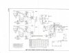
and, zekk, i didn't get an email from you, so here's the schematic...
 

Attachments

that last one was a 1MΩ, 1watt carbon film resistor. i need four of them for my sa-232 (R60, R62, R76, R79), and *all four* from mouser are waaaay out of spec. they measure between 300kΩ and 400kΩ, and they're supposedly brand new. i am going to call mouser today and see what's up with that. i am also going to have my friends in our electronics shop (down the hall) check them on *their* meter, just to know i am not nuts, or my meter isn't what's wrong.

is it common for parts to be out of spec from the manufacturer? i know they don't test every part, but that's pretty egregious if i am measuring them correctly...

Your hands aren't on the resistor or meter leads when measuring are they? Human body resistance can affect the results when measuring resistances that high. I've never gotten out of spec parts from mouser before...
 
Hey ya madwing! Hope your feelin' better:yes:Ya beat me, I have/had way to many things come up just when I thought I was $$ over:thumbsdn: will be getting to mine fingers crossed soon. Great that your doing the pic thing with the great descriptions:thmbsp::thmbsp: are you going to go over the pre/tuner as well?

Craig, has the same console born the same month:smoke:
 
Your hands aren't on the resistor or meter leads when measuring are they? Human body resistance can affect the results when measuring resistances that high. I've never gotten out of spec parts from mouser before...
i was setting them on my shorts-clad thigh. i will do them on my wooden worksurface tonight, and today on their electronics pad at the e-shop. i didn't realize i could influence the readings. i'll set up a dedicated spot (a board with a piece of double-sided tape, or something) so i don't have to hold them.

thanks, for that!

edit: i tested them on an electronics pad, and they're all bang on spec. so, note to newbies, or other assorted first-timers: test resistance on something that won't add resistance to the circuit (ie., a wooden desk, a plastic pad, etc.), and not your hand or your shorts-clad thigh.
 
Last edited:
Hey ya madwing! Hope your feelin' better:yes:Ya beat me, I have/had way to many things come up just when I thought I was $$ over:thumbsdn: will be getting to mine fingers crossed soon. Great that your doing the pic thing with the great descriptions:thmbsp::thmbsp: are you going to go over the pre/tuner as well?

Craig, has the same console born the same month:smoke:
thanks, craig. better every day (now it's just the residual chest gunge and some sinus pain). my head's clear, that's what is important.

i'll keep up the pics (will take more tonight and post) and the process...i've never done anything like *this* before, and it's *fun*.

i am not, at this point, going to mess with the pre. the only thing i've done is tested the tubes, and replaced the ones that were not as good with ones that were better. i want to get the amp running, so at the very least i can listen to music in my shop...i have projects backed up behind the amp (things promised) i want to make while listening to the beauty of tooobs.

bill
 
Thanks Bill ! Appreciated it.

Puzzled by those giant size resistors and there are two where it's connected parallel. Noticed it's also in your's and that confirmed it's intentional. And as for the 100+100 uf @25WVDC, do you know why it was connected together to form a 200uf?

Hope I'm not hampering your progress!?
 
Last edited:
Just to show what can be done with Pilots to give them wife appeal as my friends wife referred to my friends integrated as "Butt Ugly"

We took basically the same amp only with 6db of feedback vs 12db in the 232 your doing here. The 232 inverts phase.

The EL84 produces more than twice the gain of many pentodes so it really does need the 12AU7 at all.

I redesigned The Pilot Integrated that a friend brought to me after I saw this simple power amp circuit. The Integrated had very bad switch's and pots a real mess! But I bypassed the front end and we listened to the basic power amp and really liked what was heard through Pro AC Response II's it was so good that we did a complete rebuild using the old iron that was repainted in piano black finish, the top is solid polished brass with a walnut wood skirt and a copper bottom plate, ceramic sockets, Edison Price speaker posts, He wanted carbon resistors. Be careful with these they will change value if over heated! The power supply used Cerafine capacitors some 600uf's and GZ37 rectifier.

Later I had a hunch and removed the 100 ohm resistor out of the power supply path for greater dynamic authority and with my new lay out of the circuit it had substantially lower noise floor.

el84powerampfk1.jpg


pilotol2.jpg
 
Thanks Bill ! Appreciated it.

Puzzled by those giant size resistors and there are two where it's connected parallel. Noticed it's also in your's and that confirmed it's intentional. And as for the 100+100 uf @25WVDC, do you know why it was connected together to form a 200uf?

Hope I'm not hampering your progress!?
hey, des. no worries.

those are intentional; the schematic shows it that way, too.

i am using two 100µf/100WVDC caps, tying together the negatives and and using the positives independently as they were meant to be used. the twinned negatives go to a single ground lug on the V9 tube socket. i don't know enough about capacitors to know why connecting the grounds would change their capacitance, and why that would be a design feature. i *think* it was just a convenience measure to use a single cap rather than two...but am resigned to thinking i am wrong. i am keeping it the way it was designed, though.

i have V9 completely cleared of attachments, and tonight (late) will begin to clean it up, removing the solder and the bits of snipped wire. i am going to do that with every socket, making sure every joint is hot, rather than cold and old...
 
Just to show what can be done with Pilots to give them wife appeal as my friends wife referred to my friends integrated as "Butt Ugly"

We took basically the same amp only with 6db of feedback vs 12db in the 232 your doing here. The 232 inverts phase.

The EL84 produces more than twice the gain of many pentodes so it really does need the 12AU7 at all.

I redesigned The Pilot Integrated that a friend brought to me after I saw this simple power amp circuit. The Integrated had very bad switch's and pots a real mess! But I bypassed the front end and we listened to the basic power amp and really liked what was heard through Pro AC Response II's it was so good that we did a complete rebuild using the old iron that was repainted in piano black finish, the top is solid polished brass with a walnut wood skirt and a copper bottom plate, ceramic sockets, Edison Price speaker posts, He wanted carbon resistors. Be careful with these they will change value if over heated! The power supply used Cerafine capacitors some 600uf's and GZ37 rectifier.

Later I had a hunch and removed the 100 ohm resistor out of the power supply path for greater dynamic authority and with my new lay out of the circuit it had substantially lower noise floor.

el84powerampfk1.jpg


View attachment 88864
that's pretty impressive, set. and pretty, too. is that attachment the schematic of the "revised" sa-232 shown? or of the revisions you made to the pilot integrated?

guess i'll have to find a second 232 and see how it will sound with that kind of redesign...in time :)
 
Back
Top Bottom