shimniok
Super Member
I am lazy. There is NO way I am going to manually clean the hundreds of classical records I just acquired. So instead of going thru all that work, it makes way more sense to spend dozens and dozens of hours building a record cleaning machine from scratch... 
But wait... why just build a manual machine when I can spend even more time adding a microcontroller and programming the device to automatically spray, scrub, and vacuum records, all by itself! Ok, ok, I know this has been done, it's your basic one-side automatic RCM. And there are lots of posts on here by far more skilled individuals who have built nice RCMs.
So I am calling mine a record cleaning robot. A mechanical minion. Silicon slave. Sort of a vinyl cleaning kobold, like the mythical Biersal, only for records!
Ok, it probably won't be able to pick the record out of my hand with a clenching plastic fist and pull it out of the cover and sleeve and scrub away with charming personality like some kind of Rosie the Maid... at least not for some time.
But I guarantee I'm not stopping until I can -- at a minimum -- slap a record on the platter, press one button, wait a few minutes, and pull a perfectly sparkly half-cleaned record back off, with no other intervention.
Laziness requires a lot of hard work! So far: just finished a workable chassis last night that may end up being a prototype but it'll let me prove out the other subsystems. Right now it is totally fugly, yes, but I promise it won't stay gruesome for too long...
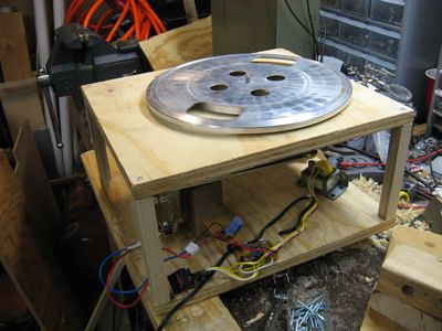
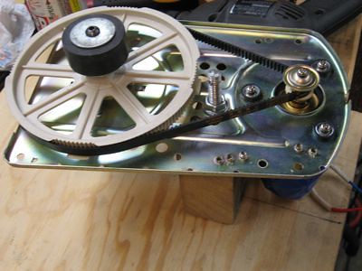
The plan: gutted bread machine supplies drivetrain for the platter and some electronics. Free platter from a Garrard (thanks Ed). MOSFET driver(s) interfaced to the MCU. More electronics form an old, dead, linear tracking TT. $2 portable handheld vacuum with fittings and hose to suck the fluid from the LPs, controlled via Triac interfaced to microcontroller. MCU will either be a discontinued Pololu Baby Orangutan based on an AVR ATmega168 or just a raw 168. Fluid dispensed by... automotive window washer squirter and garden drip system sprayer? Hmmm :scratch2:
If anyone's interested I'll post more detail on the chassis. I don't want to bore anyone Meanwhile I've been writing up the build on my robotics tinkering blog.
Here's a video version of the build up thus far: http://www.youtube.com/watch?v=r6jwGVVszFc
But wait... why just build a manual machine when I can spend even more time adding a microcontroller and programming the device to automatically spray, scrub, and vacuum records, all by itself! Ok, ok, I know this has been done, it's your basic one-side automatic RCM. And there are lots of posts on here by far more skilled individuals who have built nice RCMs.
So I am calling mine a record cleaning robot. A mechanical minion. Silicon slave. Sort of a vinyl cleaning kobold, like the mythical Biersal, only for records!
Ok, it probably won't be able to pick the record out of my hand with a clenching plastic fist and pull it out of the cover and sleeve and scrub away with charming personality like some kind of Rosie the Maid... at least not for some time.
But I guarantee I'm not stopping until I can -- at a minimum -- slap a record on the platter, press one button, wait a few minutes, and pull a perfectly sparkly half-cleaned record back off, with no other intervention.
Laziness requires a lot of hard work! So far: just finished a workable chassis last night that may end up being a prototype but it'll let me prove out the other subsystems. Right now it is totally fugly, yes, but I promise it won't stay gruesome for too long...
The plan: gutted bread machine supplies drivetrain for the platter and some electronics. Free platter from a Garrard (thanks Ed). MOSFET driver(s) interfaced to the MCU. More electronics form an old, dead, linear tracking TT. $2 portable handheld vacuum with fittings and hose to suck the fluid from the LPs, controlled via Triac interfaced to microcontroller. MCU will either be a discontinued Pololu Baby Orangutan based on an AVR ATmega168 or just a raw 168. Fluid dispensed by... automotive window washer squirter and garden drip system sprayer? Hmmm :scratch2:
If anyone's interested I'll post more detail on the chassis. I don't want to bore anyone
Meanwhile I've been writing up the build on my robotics tinkering blog.Here's a video version of the build up thus far: http://www.youtube.com/watch?v=r6jwGVVszFc