• The move to the new server is done. There are some software and database maintenance updates in process. This has us passing the hat around to help out. We appreciate any donations. Seriously, even a dollar helps. The payment page may be found here - https://www.audiokarma.org/support.html

running a XO rebuild parts list by ya...

cdfac

AK Subscriber
Subscriber
I'm rebuilding the massive crossovers of some Infinity QLS1s in the near future and I've been working up a parts list, which has gone through a few iterations but may finally have settled. Now I'd like some input if I'm making a bad choice with the money I have to work with. My budget is basically $300, which I've almost reached. Schematic for reference:

http://infinity-classics.de/infinity/technik/manuals/Quantum_Line_Source_1_technical_sheet.pdf

For resistors throughout, 5.6 Ohm 25W wirewound ones from Madisound.

For the woofer: for caps (1100 and 1400 uF) I'm looking at a combo of Bennic and P.E. NPEs, and for inductors the Erse 16AWG Super-Qs.

For the midbass: a 40uF Solen and 18AWG 5mH I-core inductor from PE.

For the midranges: 2x6.8uF Daytons and 18AWG 0.4mH "perfect layer" air-core inductor.

For the tweeters: Dayton caps of 1.5/2.0/2.7uF (selectable XO point).

Also considering upgrading the binding posts to some fairly inexpensive Dayton BPGS-25Gs, but I'm not sure what internal wiring to go with. To be safe I'm going to need at least 12 feet each for the tweeters and midranges, 6 feet for the midbasses, and 8 feet for the woofers. I was thinking either the 16AWG Dayton OFC or the Belkin Pro (very inexpensive) from P.E. I could probably afford the bump up to Monster XP if that gets me anywhere. Is there anything else in the price range up to $40-$50 for a 50ft spool that I should be looking at (or not looking at)?

I really appreciate the help, thanks.

Chris
 
Register to hide this ad
Be careful replacing inductors, you can throw off the balance of the speaker, plus the fact that inductors usually don't go bad.

If you do replace any, make sure the DCR's are very similar. Less DCR=less resistance=more sound. So unless you want to change the voicing, stick with the original values or just reuse the original parts. Don't get me wrong, if you listen at loud enough levels, going from a iron core to an air core inductor can make an improvement.

Also, avoid Monster unless you can get it for cost...you'll do just fine with PE's wire.

Otherwise, I've never seen capacitor values that high in a speaker before. :yikes:

Best of luck on your build, keep us updated.
 
Be careful replacing inductors, you can throw off the balance of the speaker, plus the fact that inductors usually don't go bad.

If you do replace any, make sure the DCR's are very similar. Less DCR=less resistance=more sound. So unless you want to change the voicing, stick with the original values or just reuse the original parts. Don't get me wrong, if you listen at loud enough levels, going from a iron core to an air core inductor can make an improvement.

Also, avoid Monster unless you can get it for cost...you'll do just fine with PE's wire.

Otherwise, I've never seen capacitor values that high in a speaker before. :yikes:

Best of luck on your build, keep us updated.

yeah, it's pretty crazy. those caps are highpass filters for the DVC Watkins woofer. the larger value is probably for a rolloff at something like 20Hz. these woofers will play lower than that (but not in a very controlled way) in this cabinet. i'll avoid the Monster and stick to PE. i also think i'll take your advice and avoid replacing the inductors for now and see what improvement just the caps and resistors give. that will reduce my costs a lot. i'm going to be biamping, so i don't think that i'm going to be running into any problems (more likely the contrary) by lowering the DCR, but we'll let sleeping dogs lie.
 
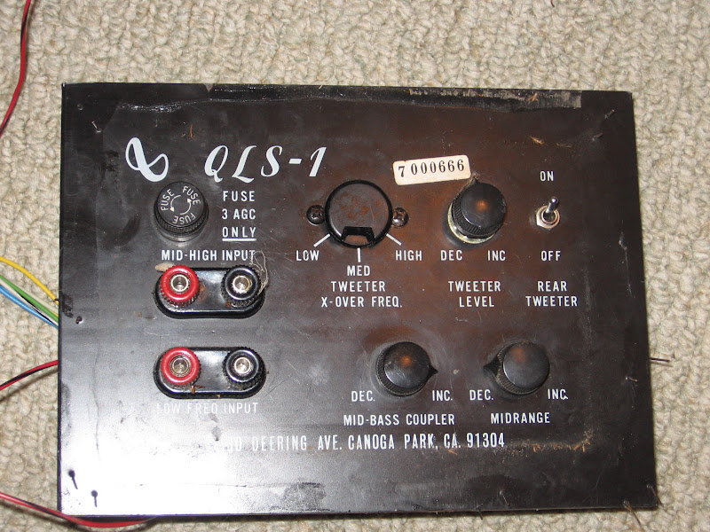
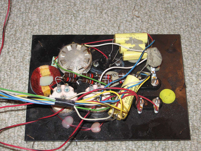
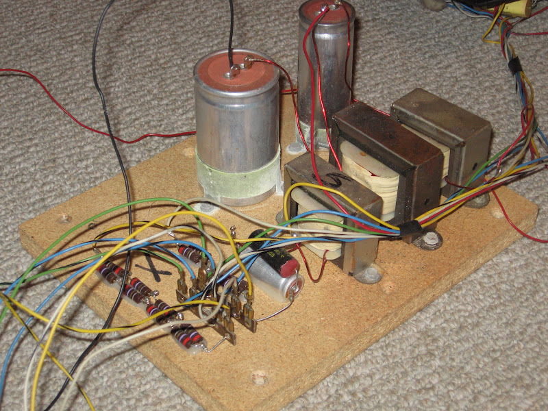
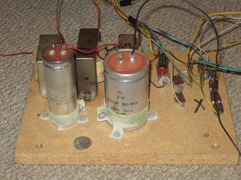
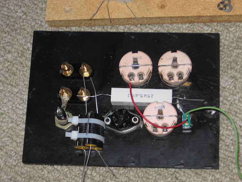
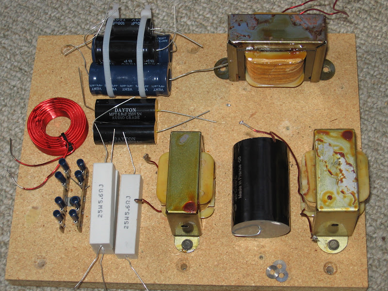
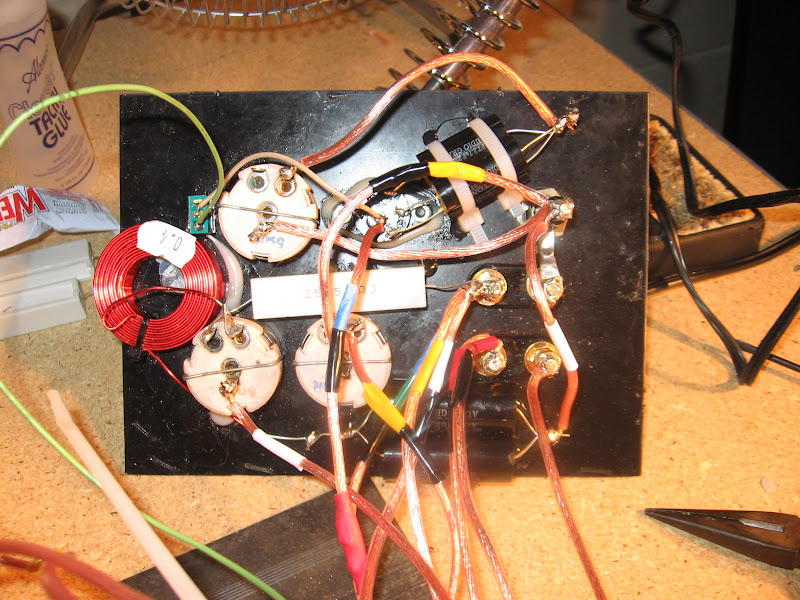
just for reference, here's what I'm starting with. i'm going to do the work on a spare set of XOs i pulled from 2 parts speakers, then i'll swap XOs when i'm done. the bigger woofer cap is larger than a lot of amplifiers' PS caps - there's a nickel in there for scale.

IMG_1965.JPG

IMG_1964.JPG

IMG_1963.JPG

IMG_1962.JPG
 
Got the parts this morning. Here's a mockup. A lot cleaner than before, although the wires are in yet. Look at the size of that Solen 40uF!

IMG_1966.JPG

IMG_1967.JPG
 
Your posts are very timely. I am in the planning stages of rebuilding the XOs in some 30 year old IMFs that I got recently. Your project is the encouragement that I need!
 
good to hear. i'm not the best solderer, but i got most of the XO above done last night. two mistakes, though - tapping the center of a pot when i needed to tap a side, which i'll have to undo, and putting a cap and inductor on the back side of a circuit instead of on the front, which should make no difference. i'll this side done tonight but i don't have an amp now to test it with. the end of spring break will fix that, at least.
 
Got both of the XOs done now. The difference appeared to be not so subtle when I installed the first completed one and A/B'ed with the original still installed in the other speaker. The sound was less veiled, the treble seemed to have more definition, and the sound quality at low volume seemed to be improved. I believe vocals and upper midrange are less muddy, as well, though they were still very good before.

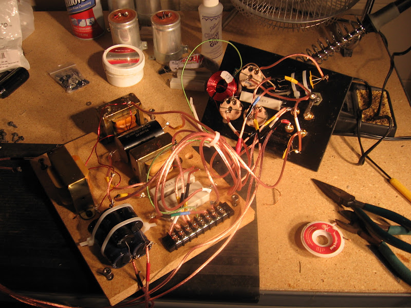
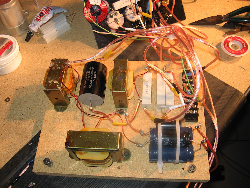
Here are some pics of the final product. I'm pretty happy with how it turned out.

IMG_2010.jpg


IMG_2011.jpg


IMG_2012.jpg
 
Last edited:
it's interesting how capacitor sizes have changed over time. notice how much smaller the new woofer electrolytics are (navy and black). in contrast, the new 40uF poly midbass cap is enormous compared to the original Callins one, which was just a bit bigger than the new white sand-cast resistors.
 
I'm also in the process of rebuilding the crossovers in my Fisher XP-10's. I think working on basic crossover circuits like this will give me the push I need to work on a few other electronic projects. I think getting over the stigma is half the battle so you feel more comfortable.
 
Hi Chris,
I'll jump in to let you know how envious I am of your handywork!

I just picked up a pair of QLS-1's last Saturday and will be looking at recapping my crossovers soon. You may be interested to see yet another version of these crossovers here, I'll post some driver differences in your other thread. I don't know if the history of these can be followed by serial numbers, but mine are 7000616 and 7000085. Obviously an unmatched pair but at least I got a left and right!
If the lower serial number denotes a earlier version there was a time before the large can capacitors were available. I haven't totaled the values of the 9 caps in the 7000085, but the right has the 1600mf and 1400 mf I think you mentioned from your donor QLS1 parts.
If you have your crossover architecture drawn up I'd be grateful for a copy!

Jim
 

Attachments

  • XoverLeft.jpg
    XoverLeft.jpg
    128.4 KB · Views: 124
  • XoverRight.jpg
    XoverRight.jpg
    115.9 KB · Views: 134
  • QLS1 system1.jpg
    QLS1 system1.jpg
    77 KB · Views: 110
I've been trying to figure out the crossover design based on the topology shown on the datasheet Chris posted above and I'm just not getting it. Following that datasheet and the wiring of the drivers, I think I'm finding the following:
Emit section, 3 - 3 each series sets, 4 ohm drivers, wired parallel = 4 ohms (1st order xo, 8 drivers in phase, 1 rear out of phase)
Midrange section, 2 - 3 each series sets, 8 ohm drivers, wired parallel = 5.33 ohms + 2.7 ohm resistor = 8.0 ohms (2nd order xo, 6 drivers in phase)
Mid-bass coupler, 1 driver = 8 ohms(? stock) (2nd order xo, out of phase)
DVC woofer, 1 driver = 4 ohms/4 ohms(?, need to check) (2 - 2nd order xo's, in phase).
Please comment if I've got this screwed up, I've run the formulas based on these assumptions and can't get the component values to add up to the crossover points listed on the datasheet. If this is close to correct, how can these be considered 4 ohms nominal? Most importantly for my purposes, what is the stock impedance or DCR's of the mids and the mid-bass? I have Franken-QSL's that require some tweaking.
 
I've been trying to figure out the crossover design based on the topology shown on the datasheet Chris posted above and I'm just not getting it. Following that datasheet and the wiring of the drivers, I think I'm finding the following:
Emit section, 3 - 3 each series sets, 4 ohm drivers, wired parallel = 4 ohms (1st order xo, 8 drivers in phase, 1 rear out of phase)
Midrange section, 2 - 3 each series sets, 8 ohm drivers, wired parallel = 5.33 ohms + 2.7 ohm resistor = 8.0 ohms (2nd order xo, 6 drivers in phase)
Mid-bass coupler, 1 driver = 8 ohms(? stock) (2nd order xo, out of phase)
DVC woofer, 1 driver = 4 ohms/4 ohms(?, need to check) (2 - 2nd order xo's, in phase).
Please comment if I've got this screwed up, I've run the formulas based on these assumptions and can't get the component values to add up to the crossover points listed on the datasheet. If this is close to correct, how can these be considered 4 ohms nominal? Most importantly for my purposes, what is the stock impedance or DCR's of the mids and the mid-bass? I have Franken-QSL's that require some tweaking.

first of all, sorry it took so long to write back. well, the wiring is pretty difficult to interpret for the first time, but with some help it will all make sense.

the tweeters and mids are both wired so that each nearest pair is in series, with all pairs in parallel to each other. don't worry so much about the resulting DCRs, but you should know that the proper EMIT range is 4-6 Ohms, the mids between 7 and 8 Ohms, the midbass around 7 Ohms, and the two woofer coils at about 2 Ohms and about 5 Ohms. nominally, you have to consider the impedance that includes how the inductors and capacitors behave at different frequencies, so with those you get something near 4 Ohms. in an old test report, they found that these never dropped below 2.5 Ohms, so the challenge isn't so much to have an amp stable down to extremely low impedances, but because of the low efficiency you need to have massive power and lots of reserves to do the Watkinses justice without clipping and killing the EMITs. about 500Wpc @ 8 Ohms should do ;) of course, most amps that meet these other requirements are also stable down to 2 or even 1 Ohms, so we're sort of mincing words.

your best aid in wiring is to pay close attention to the colors. i found my later XO to wired exactly like the schematic once i was able to trace the circuits out, so the online schematic is really all you need. the simplest thing to do is start at one speaker binding post and follow one wire through everything it does, writing it all down.

one hint. if you look at the schematic you'll see the pots represented as resistors with lines leaving the top. that line leaving the top is the center tap, which is usually at the center of the back of the pot. most of the time, this is what eventually goes to the speaker. if all three taps have something wired to them, that means that one of the sides is connected to a resistor that then goes straight to ground, which you'll see in the schematic. i was careful to make separate pot diagrams of what was actually in the speaker before i disconnected everything.

another hint. when redoing stuff, stick to the order represented on the schematic. makes your own work easier to follow and check on, and it will ensure that everything sounds right.

as you have more questions, let me know. once you pull out the XOs (which is pretty easy since the wires going to the drivers disconnect quickly, the wood plate unscrews, and the back plate can be freed from its adhesive with some force and patience), expect a few weeks of downtime unless you're a quick solderer and a quick study.
 
Thanks for the advice Chris, that'll surely help! My biggest issues at this point are to remove and clean the pots which are intermittent on the right and appear to be jumped on the left, and to decide how I might modify the midrange crossover to compensate for the Philips midrange drivers in my cabinets. Caps and resistors are on the way from Madisound too. I've tapped a fixed L-pad in each midrange circuit for now and they're sounding better.
Jim
 
Nope, I looked right at the mfr's mark yesterday and they aren't Aetna Pollack. I can't remember what name was on there (alziemers onset) though they look very similar. I believe AR's are 16 ohm potentiometers, these are 5 ohm pots. I'm just getting my head around the difference 'tween pots and L-pads thanks to the AR thread.....
http://www.audiokarma.org/forums/showthread.php?t=71133
.....which provides alot of useful info on them.

The Infinity pots are single wiper wire-wound ceramic.

Here's my question...WHY use a pot rather than a L-pad in the QLS1?

Are those pots Aetna Polack as in Vintage AR speakers?
 
Nope, I looked right at the mfr's mark yesterday and they aren't Aetna Pollack. I can't remember what name was on there (alziemers onset) though they look very similar. I believe AR's are 16 ohm potentiometers, these are 5 ohm pots. I'm just getting my head around the difference 'tween pots and L-pads thanks to the AR thread.....
http://www.audiokarma.org/forums/showthread.php?t=71133
.....which provides alot of useful info on them.

The Infinity pots are single wiper wire-wound ceramic.

Here's my question...WHY use a pot rather than a L-pad in the QLS1?

Isn't it to provide constant Ohm's in crossover vs L-Pad that changes? I thought changing Ohm's moves crossover freq?
 
Thought I would bring this old thread up since I am recapping my Infinity QLS-1s' I noticed that both Jims and Chris's crossovers used a series of carbon resistors while my pair used ceramic resistors. Also although the main Watkins caps are of the same value the 1000 uf cap on his is smaller than the one on my pair, along with the one inductor is a bit new looking.

I am now going cap shopping!


001-3.jpg
 
Back
Top Bottom