• The move to the new server is done. There are some software and database maintenance updates in process. This has us passing the hat around to help out. We appreciate any donations. Seriously, even a dollar helps. The payment page may be found here - https://www.audiokarma.org/support.html

My 6L6GC amp build thread

Maxxarcade

Active Member
This is going to be the thread I use for anything related to my amp project.

What I am building, is a Harman Kardon HK-250 based amp, with a larger power supply, pre-amp, multiple inputs, and some other tweaks.

Main parts list:

Hammond 17x10x3 steel chassis
Antek AN-3T325 power transformer
1N5408 full wave diode rectifier
Hammond 2.5H 300ma choke
50uf and 500uf cap banks
Edcor CXPP60-MS-6.6K OPTs
JJ 6L6GC matched quad
GE 6SN7GTB driver/inverter tubes
Sylvania 6SL7GT preamp tubes
NOS Amphenol brown octal sockets
NOS Alco solid aluminum knobs, black or plain depending on chassis color

The preamp is based on a circuit from an RCA manual and also handles the tone controls.

There will be 4 line inputs, a tape loop with LED indicator, and an auxiliary line output for connection to PC or other device. I may also add a headphone circuit with a DPDT switch and dummy load to keep the impedance low enough for the amp.

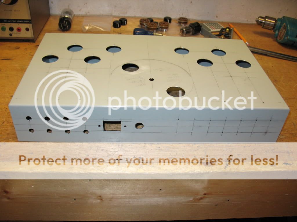
All parts are on order or on hand, and work has begun on the chassis. Center pilot holes for the OPT's, power transformer, 6L6GC's, and 6SN7's are marked and drilled. Next I will decide the placement for the 6SL7's and other hardware.
IMG_3055.jpg


I want to thank everyone here who has helped me get this far. This is my first DIY tube amp, and I've learned so much by doing this!
 
Last edited:
Register to hide this ad
It will be interesting to compare notes, once Max and I both get done. I'm doing a very similar amp (once I get to building it, it's almost ready to be started) with probably the same output circuit topology and output transformers, but with a Marantz 7 preamp (without tone controls, though) line stage and a modified (direct-coupled) RCA phono stage, and using the chassis and power transformer from a Stromberg AU-35. Mine will be with all-Loktal tubes in the preamp... maybe in the amp too, if it can handle the voltages. Otherwise, a nice pair of Sylvania 6SN7GTBs will go in the amp part (again, very like Max's amp)...

I'll put in a bet for the pool... I'm guessing we'll get around 35w/ch? If B+ winds up over 440V, maybe even 40-45w/ch?

Regards,
Gordon.
 
It will be interesting to compare notes, once Max and I both get done. I'm doing a very similar amp (once I get to building it, it's almost ready to be started) with probably the same output circuit topology and output transformers, but with a Marantz 7 preamp (without tone controls, though) line stage and a modified (direct-coupled) RCA phono stage, and using the chassis and power transformer from a Stromberg AU-35. Mine will be with all-Loktal tubes in the preamp... maybe in the amp too, if it can handle the voltages. Otherwise, a nice pair of Sylvania 6SN7GTBs will go in the amp part (again, very like Max's amp)...

I'll put in a bet for the pool... I'm guessing we'll get around 35w/ch? If B+ winds up over 440V, maybe even 40-45w/ch?


Regards,
Gordon.

PSUD2 shows 435v at 100ma, and 411v at 250ma for my power supply config. I hope I get at least a little more power than the original HK-250 had to offer.:scratch2:
 
I've built this circuit into a couple of homebrews. I really like it, especially the single tube up front (double triode). Last time I used the 6SN7 to keep it all octal, which seemed fine. IMO the power supply was defiantely the weak link on the original HK.
 
Yep... more PS capacitance (and optimally, a choke) would seem like it would go a long way...

Regards,
Gordon.
 
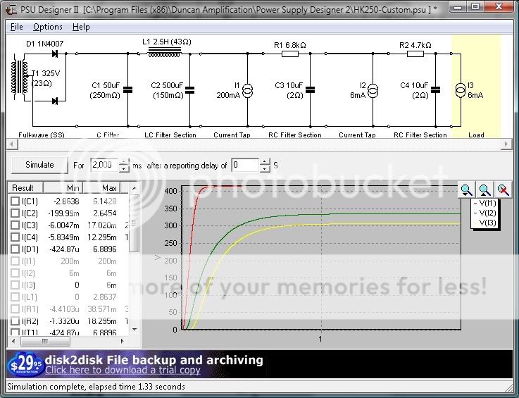
How does this look?

I used the same resistor values as the original HK250 PSU for the two lower B+ outputs, but I'm not sure what to use as the load current.

Since I'll also be running the 2 6SL7 preamp tubes on this PSU, that weren't in the original design, I'll probably need to make a couple changes in the resistor values.

I'll be using 1N5408 diodes instead of the 1N4007 shown.

PSU.jpg
 
Last edited:
Power supply looks very good - well damped with the 500uF after the 50uF. One thing to try - make the main current source stepped at 1s, going to 250mA. See how much the voltage drops. Then, you can increase the first cap slightly. I'd try 100uF first. Voltage drop between idle (200mA) and peak (250mA) can be minimized as best you can, without allowing ringing as a result of the transient. Basically: If the first cap is way-bigger than the second cap, it will bounce too much and overshoot. But if too small, the voltage drop will be greater. The SS diodes can handle a big cap fairly well.

Also, the 10uF caps may prove to be too small in practice. I don't see any reason not to use 50uF instead. Unless you want to go for film. :)
 
Power supply looks very good - well damped with the 500uF after the 50uF. One thing to try - make the main current source stepped at 1s, going to 250mA. See how much the voltage drops. Then, you can increase the first cap slightly. I'd try 100uF first. Voltage drop between idle (200mA) and peak (250mA) can be minimized as best you can, without allowing ringing as a result of the transient. Basically: If the first cap is way-bigger than the second cap, it will bounce too much and overshoot. But if too small, the voltage drop will be greater. The SS diodes can handle a big cap fairly well.

Also, the 10uF caps may prove to be too small in practice. I don't see any reason not to use 50uF instead. Unless you want to go for film. :)

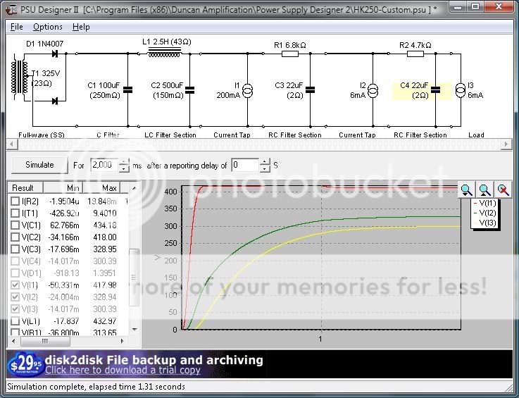
I tried 47uf for the last two caps and it did not work. 22uf works though. The original HK250 PSU only had 8uf caps there.

Changing the first cap to 100uf gave an increase of about 6 volts to the RMS values at the loads.

Main B+ load (I1) is stepped at 1 second from 200 to 250ma.

Here are the results with the changes:


PSU2.jpg


Not sure I want to buy more caps to gain a couple volts, but I will if I need to order other parts at the same time.
 
Last edited:
If you already have the right caps handy - I wouldn't worry or change a thing. The difference would be pretty negligible. Just slightly reduced drop from 200mA load to 250mA load. But performance is already excellent with the solid state supply!
 
When you say it "did not work" with caps bigger than 22uf... were you getting error messages like "XXX has pulled XXX below zero volts at time XXX" or something like that?

That's usually a sign of impending ringing, AFAICT. Though, I've seen some power supplies of some well known, very good-sounding amps that sometimes "fail" that way when modelled in PSUD2... the simulation is somewhat simplified, compared to the additional loads and damping effects present in "real-world" components...

Regards,
Gordon.
 
When you say it "did not work" with caps bigger than 22uf... were you getting error messages like "XXX has pulled XXX below zero volts at time XXX" or something like that?

That's usually a sign of impending ringing, AFAICT. Though, I've seen some power supplies of some well known, very good-sounding amps that sometimes "fail" that way when modelled in PSUD2... the simulation is somewhat simplified, compared to the additional loads and damping effects present in "real-world" components...

Regards,
Gordon.

Yep, that was it. Would there be any benefit to having bigger caps for the lower voltage sources? I was under the impression that the 500uf would take care of most noise/ripple anyhow. Though I suppose if the preamp had a lot of current swing, it could use more uF.
 
If the circuit is designed for 10uF caps, you can use 10uF without worry - it's more about decoupling the stages than ripple - and more important with a high gain input stage (which isn't a problem with 6SN7 are involved). Can even go with Solen films if you want to get "fancy".
 
My parts have not come in from AES yet, but I want to start working on the back panel layout...

For those of you who have used the insulated type RCA jacks that I ordered, is 1" centers a good spacing for them, or should I go a bit larger?
 
1" spacing should be fine. Enough room for even the most bulky RCA plugs.

Truthfully, with respect to the caps... I'd be inclined to just go with the 22uf in the final two positions. No reason to not bump it up from the stock value. Should work fine. PSUD2 is a bit of a "whiner" sometimes about these things, IME... :D If it passed it, it should be absolutely fine.

You might want to bypass the 22uf caps, though... maybe something like a garden variety .1uf cap (or any remotely similar value). Never a bad idea... decoupling can be improved at high frequencies, sometimes, by doing this.

Regards,
Gordon.
 
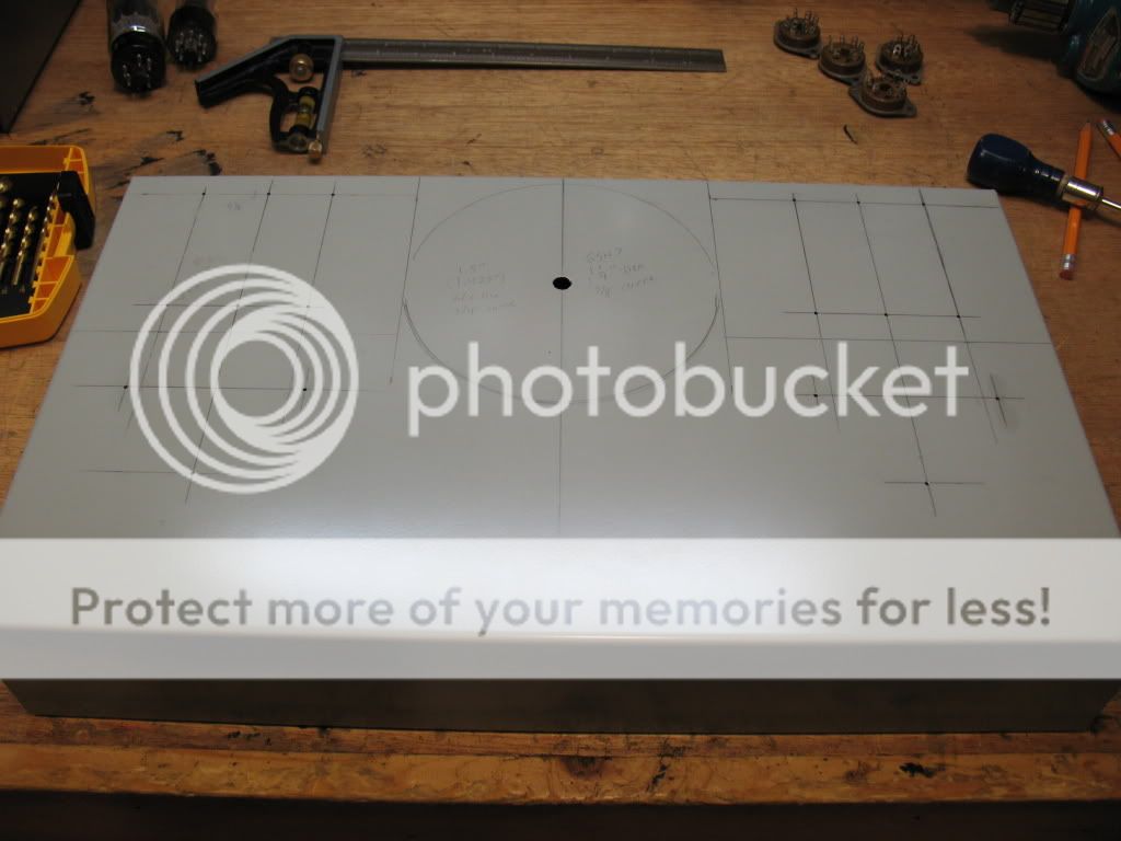
With some minor tweaking to the IEC and fuse holder positions, the back panel is now laid out and drilled. I only have the pilot holes for the RCA jacks so far, because I don't know what size hole they will need. Everything else (on the back panel) is at final size.

Also drilled the tube socket and PT wire holes.

Now I just have to design and drill the front panel, and the chassis will be ready for painting. After that, then the fun stuff starts. :D

I had some issues with my square being slightly not-square, so some things got a hair off center. Maybe 1/32" or so, but it still makes it not perfect...

IMG_3061.jpg
 
Last edited:
Should I bother with the trouble of installing a headphone circuit? I would really like one, but it would add quite a few more parts to the already cramped chassis.

If I did install one, I think I'll use a pair of relays controlled by a toggle switch up front, that would cut off all the speaker outputs and route the 8 ohm tap into a pair of load resistors (I only have 32+ Ohm headphones), then to the headphone jack.

Progress is good on the chassis. I should have it ready for paint (or powder coat) by the end of the week.
 
The only time I use headphone is with my laptop so, if it were my amp, I'd not bother with it. Where do you find the round housing for the power transformer?

I like your layout and the work you've done so far.
 
Back
Top Bottom