• The move to the new server is done. There are some software and database maintenance updates in process. This has us passing the hat around to help out. We appreciate any donations. Seriously, even a dollar helps. The payment page may be found here - https://www.audiokarma.org/support.html

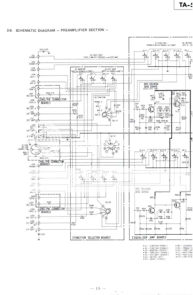
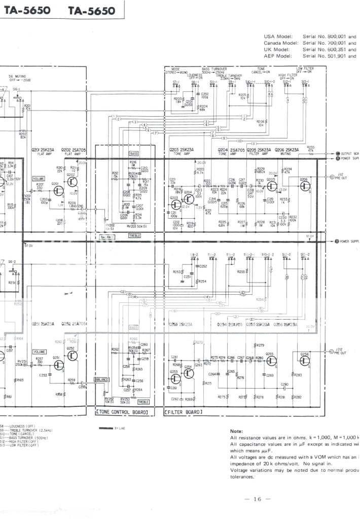
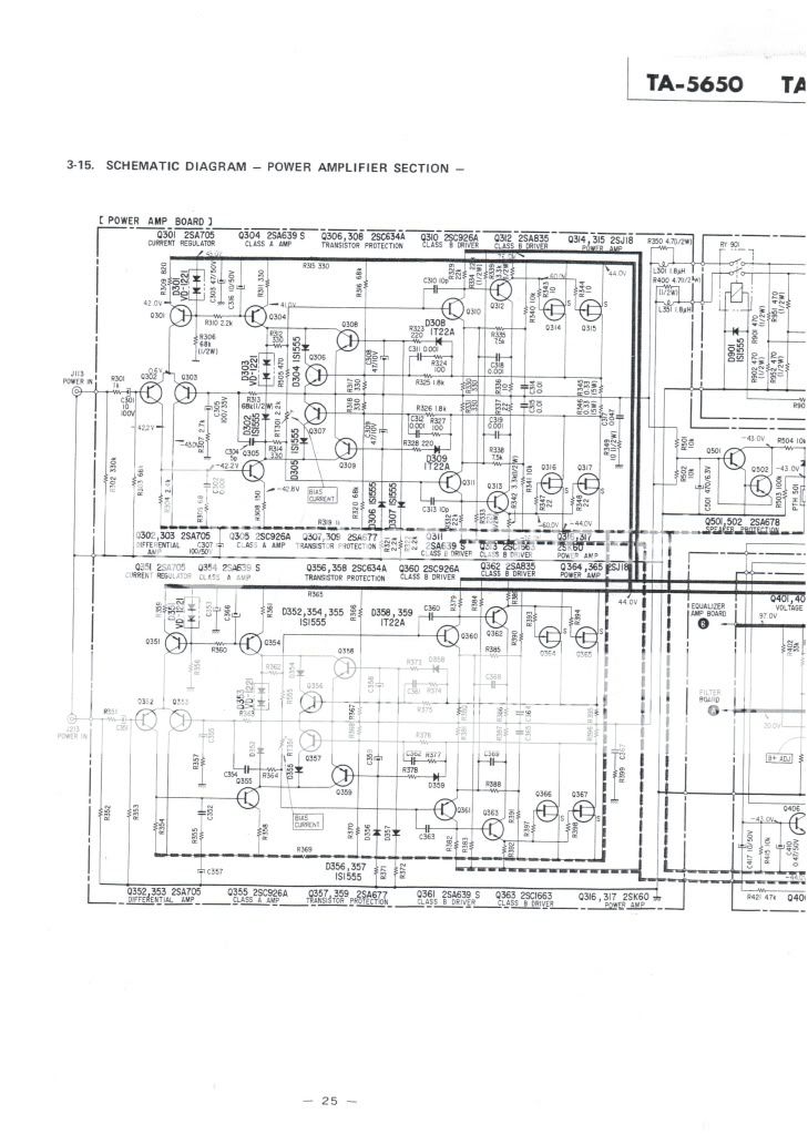
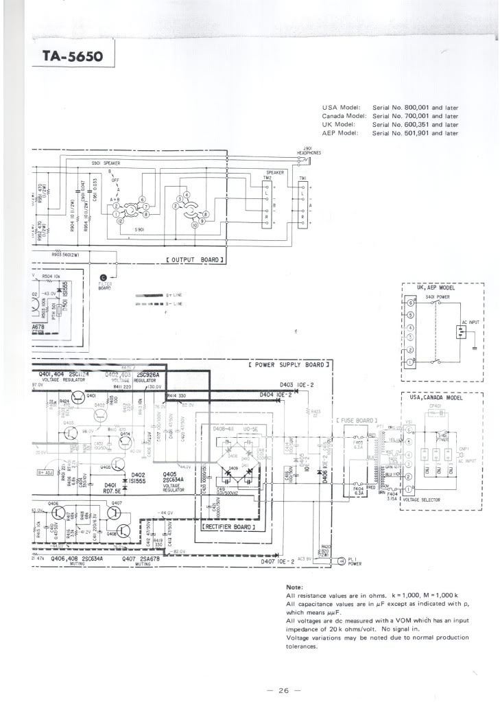
Repair WEGA V4810 / SONY TA5650 V-FET Solidstate Heaven By Helmuth.

Helmuth

Active Member
Hi People,

At my introduction I told that I yust started to repair a WEGA V4810 V-fet amplifier similar to the TA-5650 of sony. And many asked me to start a topic about it.

I discovered the TA-5650 by a Dutch audio enthusiast (Jerry) and I respect his electronic knowledge so that had to be a interesting amp.

I did some research and discovered the V-fet technology. The V-fet is the solid-state variant of what comes the closed to the the triode tube. And it is a kind of power J-fet. The preamp is a J-fet type :thmbsp:

A triode tube can amplify audio whit low distortion without negative feedback.

You shout not confuse the V-Fet whit a Mosfet. The V-fet is junction fet so there is a gate current and low Cgs different to the Mosfet, where almost no current flows types how have a large Cgs witch makes them frequency dependable.

So I would like to have a nice vintage set of the 70-80 the period where the audio equipment reached its peak. Knobs switches filters VU meters for lovers of technique a great time. People would spend a lot money on a good set.
2lcbq6u.jpg


I wanted a nice vintage set to have beside my Yaqin tube amp and stuff I build my self.

So I started looking on marktplaats a popular second hand market site in the Netherlands.
wega.jpg


And I found the WEGA V4810 problem it was defective. I am a professional electrician so that was not the problem I searched for new NOS -Vfets and found them in china. So I bought the defective WEGA V4810 and it was black that i like most:banana:.

After a while it turned out to be in a very bad state, all V-fets defective and all transistors replacement types. In the Netherlands we say how says A have to say B, what says when you start something you have to finish it.

I also have support of Jerry how also repaired a TA-5650. I found some great info on Karma. And got a tip from Piet a other Dutch guy on karma.

Here a picture of my amp.
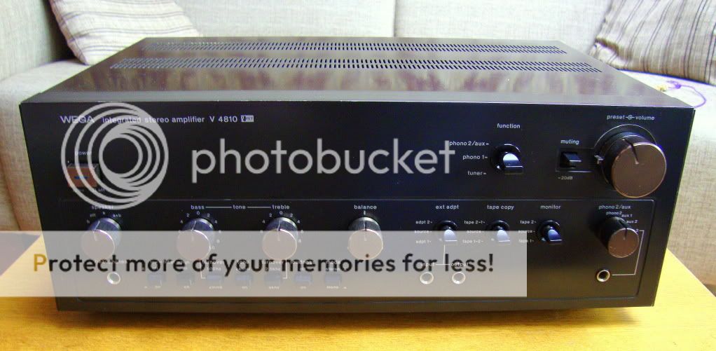
DSC00021.jpg


At the same time on marketplace the tuner how fits to the V4810 :tresbon: I couldnt believe my eyes. I had to have that one to also I found a very cool tape recorder but do not use that stuff butt looks impressive.
Here the pair after I cleaned the outside.
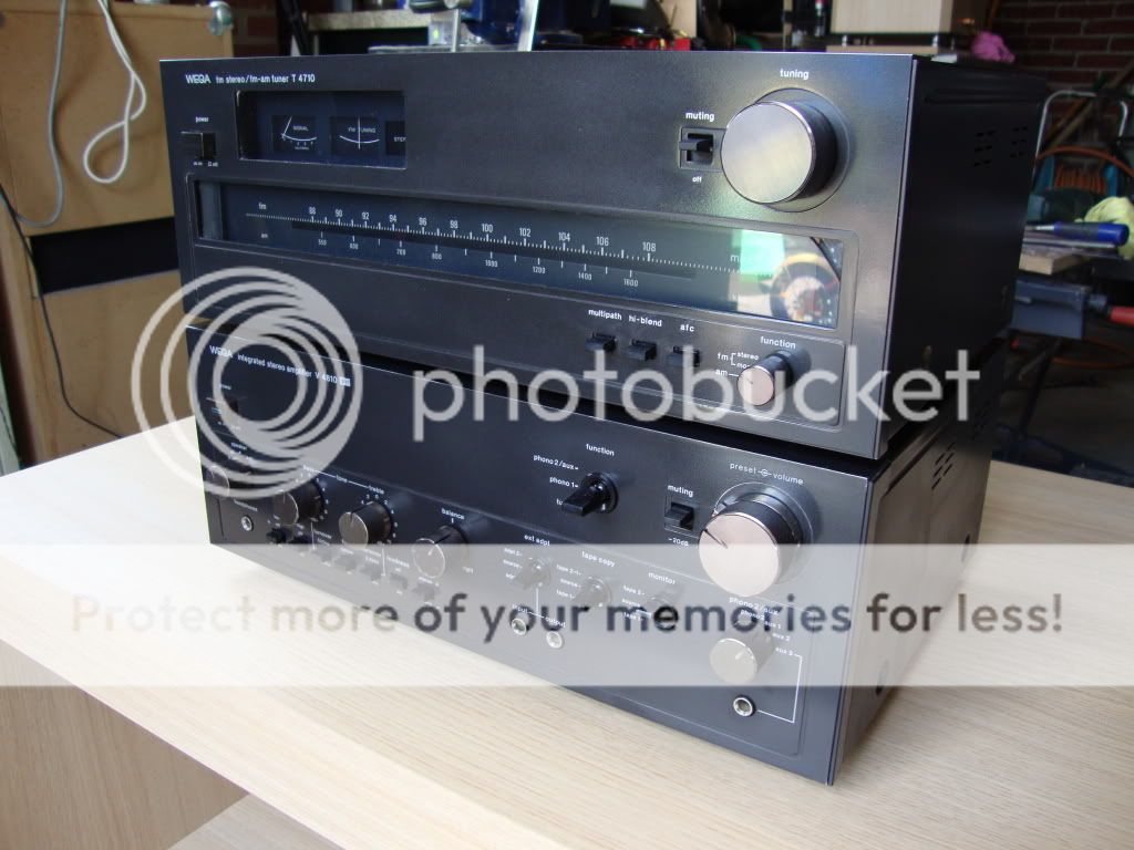
DSC00032.jpg


Nice links

http://www.passdiy.com/pdf/ZV8_power_jfet.pdf

http://www.thevintageknob.org/VFET/VFET-main.html
 
Register to hide this ad
First check-up of the end stage.

DSC00034.jpg


With no negative gate voltage the V-fet the drain source is short. A fast check of the V-Fet is a diode check from gate to drain and source.


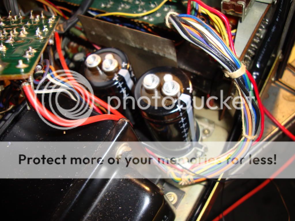
Old capasitors also worn by high temperature of the endstage, you can see that on the shrinking of the outside insulation.

DSC00042.jpg


Burned resitors.

DSC00039.jpg


DSC00038.jpg
 
Hello Helmuth. :D

They are two components which don't show-up on AudioKarma very often. :no:

Thanks for the photos and the background information. :thmbsp:

I have lived with the Yamaha B-2 V-fet amp for over 3 years.I am no longer using it(sold to my fellow Aussie AKer 'timofred').The B=2 is a wonderful sounding amp. :yes:

If I was you,I'd e-mail Axel over at 'The Vintage Knob'( as per the link you posted),and see if he'd would like to post your photos on his website.....
 
Hello Helmuth. :D

They are two components which don't show-up on AudioKarma very often. :no:

Thanks for the photos and the background information. :thmbsp:

I have lived with the Yamaha B-2 V-fet amp for over 3 years.I am no longer using it(sold to my fellow Aussie AKer 'timofred').The B=2 is a wonderful sounding amp. :yes:

If I was you,I'd e-mail Axel over at 'The Vintage Knob'( as per the link you posted),and see if he'd would like to post your photos on his website.....

I already mailed Axel.

His answer 02-06-2006

axeldahl schreef:
> Helmuth,
>
> Sony and Yamaha (and NEC) V-FET are un-obtainable anywhere on the planet.
>
> The safety mods/repairs will be brought online on TVK later on this summer, when the reshaping of the entire TVK website will have been done.
>
> cheers
> axel

Sorry for axel I repaired the amp endstage already:D and was able to purchase new NOS V-Fets in HONGKONG.;)

So do not always believe the self made expert. Axel has a nice looking site really like it he has sense for nice pictures.

Cheers Helmuth
 
A white paper on mods on the V-fet amp I found here on karma. Very important the lower bias-current to prevent a temperature avalanche effect.

I introduced the mods on my amp.

ModificatiesVfetampsony.jpg
 
Nice job ! Those WEGA units are pretty rare, dead or not.

VFETs are simply rare to find, they do exist, and you could always use a donorunit etc. Sometimes you can't find any for months, but then the past couple of months, there have been some for sale on ebay here and there. Give the guy some credit, he knows what he's talking about.
 
Nice job ! Those WEGA units are pretty rare, dead or not.
I really pleased with the wega amplifier and tuner especially the black housing and their rareness.


What I already said the end stage was unsuccessfully repaired, may more often then one attempt that I could see. Probably there was a final attempt to repair it by replacing all transistors.

The result all V-fets defective except 1 2sk60. Most of the transistors where not original ones any more. I tried to become them by brokers but they won't sell part below a quantity of 50 pieces or more.

So I searched for alternatives for my self. And use common European alternatives. It seemed to me that in America it is easier to find Japanese transistors.

I replaced the missing:

2SA705 by BC560B the european low noise type PNP.
2sc634a by BC546B
2sa677 by BC556B

2sa639s by 2SB648A a nice toshiba alternative also absolete
2sc926a by 2SD668A a nice toshiba alternative also absolete

I also replaced al capacitors by new ones. Electrolithic capasitors dry out inside after a long period. This affect increases by high environment temperature. So the capasitors of the endstage will be faster worn then the ones on the preamp board.

I advise to replace them by 105 degrees types they are designed to have long lifetime at high temperature.

They have high voltage types in the design to prevent leakage current and sound and losses produced by this current. So today capacitors are smaller you can even choose types with even higher voltage rating.

I will replace some capacitors by Wima MKS types. They have lower absorbent losses then eletrolithic capacitors, almost as good as a MKP capacitor only much smaller. So they fit in the place of the old electrolithic types. And their have an almost unlimited live expectancy.
http://www.wima.de/EN/WIMA_MKS_2.pdf

The proportionality constant relating each material's capacitance enhancement over that of a vacuum is known as its "dielectric constant."
In A.C. applications, where signal handling is involved, factors which affect the rates of both charging/discharging become key issues. Even though dielectrics with larger constants allow smaller size/capacitance devices, the properties of such dielectrics contribute deleteriously to audio signal processing.
The residual charge from dielectric relaxation is known as the "dielectric absorption." When an audio signal is passed through a capacitor the dielectric absorption prevents full charging and discharging of the capacitor at the frequency of the alternating current signal. When the signal reverses the charging on the plates the dielectric absorption presents a lagging current of the former polarity, a hysteresis effect results. This effect becomes more acute with increasing frequency.

Obviously now, not all dielectrics are equal. In audio applications it is desirable to seek the insulating material with the lowest practical dielectric absorption; hence, lowest dielectric constant, barring size and economics. Dielectric materials can be classified based on their relative polarity/polarizability properties, which the dielectric constants and dielectric absorptivities parallel.

What follows is a qualitative categorization of dielectric materials in decreasing polarity/polarizability based on chemical structure considerations (Dielectric constant data "K" given when available):

I. Metal oxide corrosion layers (electrolytic capacitors):

1) Tantalum oxide (K = 11)
2) Aluminum oxide (K = 7)

Both consist of polar metal oxide bonds possessing large permanent dipole moments, polarizability factors are negligible.

II. Ceramics and Glasses:

1) Ceramics - typically alumina or aluminosilicates (K = 4.5 - thousands)
2) Glasses - typically borosilicate (K = 4-8.5)

Similarly, the polar inorganic oxide bonds in these materials have large permanent dipole moments.

III. Minerals:

1) Mica (most common) - an alkali metal aluminosilicate, hydrate (K = 6.5 - 8.7)

Same as II.

IV.

A. Polymer films - functionally linked - ranked in order of decreasing functional linkage polarity (brackets "[ ]" indicate guess based on functional group polarity):

1) Polyesters (ex. Mylar) - ester (K = 3.2 - 4.3)
2) [Kapton - ether and imide]
3) Polyamides (ex. Nylon) - amide (K = 3.14 -3.75)
4) Polycarbonate - carbonate (K = 2.9)
5) [PEEK - ether and ketone]
6) [Poly(phenylene oxide) - PPO - ether]
7) [Poly(phenylene sulfide) - PPS- thioether]

The members of the above list can essentially be ranked based on polarity considerations alone, though polarizability considerations are significant for the latter members of the list.

B. Polymer films - carbon chain backbone - ranked in order of decreasing attached-group polarity/polarizability:

1) Poly(vinyl chloride) - PVC - chloro-substituted (K = 3.3 - 4.55)
2) Poly(chlorotrifluoroethylene) - chloro- and fluoro-substituted (K = 2.48 - 2.76)
3) Poly(p-phenyleneethylene) - Parylene - exception to list phenyl ring in backbone (K = 2.65)
4) Polystyrene - phenyl-substituted (K = 2.54 - 2.56)
5) Polyethylene - essentially unsubstituted carbon chain (K = 2.3 - 2.37)
6) Polypropylene - methyl-substituted (K = 2.1)
7) Poly(tetrafluoroethylene) (ex. Teflon) - perfluoro-substituted (K = 2.0 - 2.1)


So how lower the K factor the lower the absorbsion losses.
MKS is polyester = K3.4-4.3


The hole capasitor story you can find in this topic http://www.audiokarma.org/forums/showthread.php?t=232138&highlight=mtm+helmuth

Cheers Helmuth
 
Last edited:
First step in testing and rebuilding the endstage.

Step 1

Test of the power supply.

Remove all connectors of the endstage board.

Switch on the power. On the front plate in the right coner there is a powersupply board with one potentiometer to adjust the +20 Volt. The +97 volt shout also be automatic the right value.
DSC00203.jpg


Over R419 an R414 we must see about + and - 90Volt. Then also over the big capacitors the main powersuplly voltage - and + 45Volt.

The new EPCOS caps 10000uF 63V
DSC00181.jpg


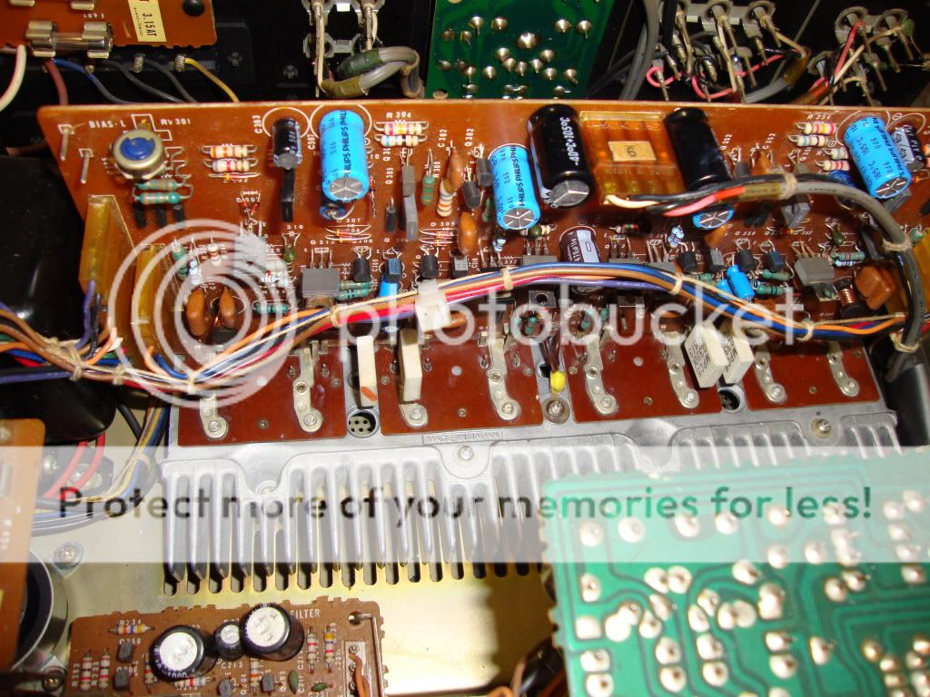
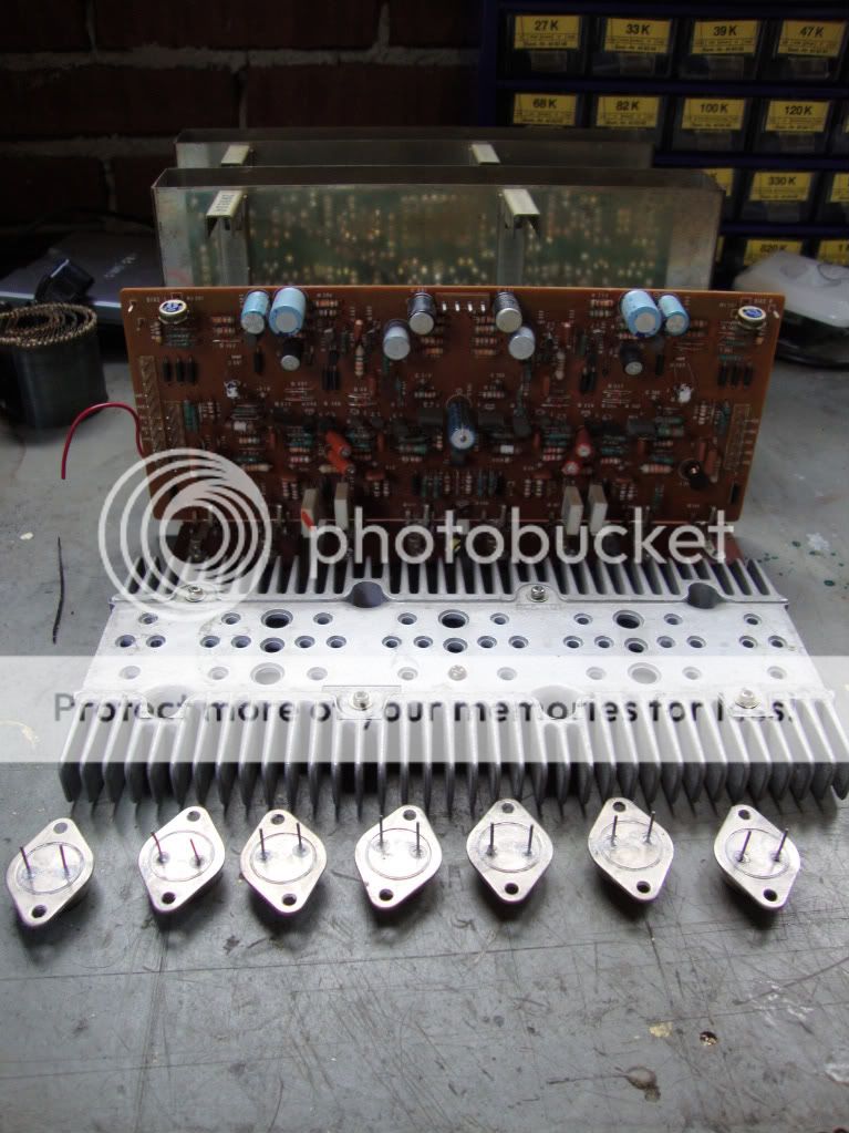
New caps and transistors on the endstage.

DSC00202.jpg


Regards, Helmuth
 
After step1 testing the voltages the 20V and 97V where OK.

But the +/- 90V and +/-45V where not symmetrical distributed and started slowly to drift.

I could not under stand what was going on??

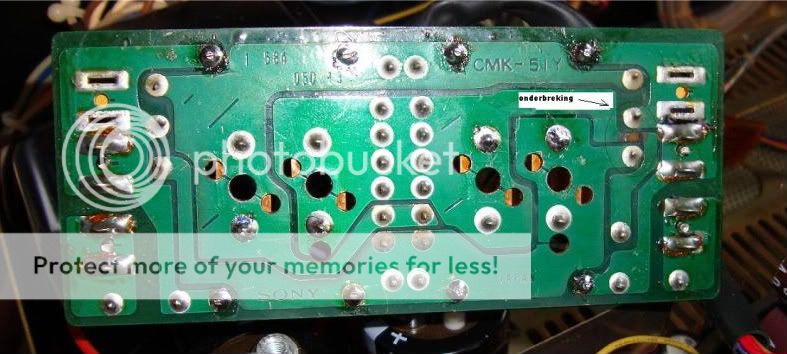
Then I discovered the problem why the previous owner couldn't fix the amplifier and blew it over and over again.:D The was a open in the circuit board of the rectifier.
Probably caused by short of defective V-fets and switching on the amp with new fuses. The open was from the junction of the to power capacitors to the ground junction of the two secondary.

Look here to see the open it is the bottom of the circuit board.
DSC00180.jpg


I hope I did other service Mann a favour here by posting this cause.

Regards and keep them running Helmuth
 
Last edited:
When step 1 is succesfull. so the 20V ,97V, +/-90V and +/-45V are OK we can go to the next step.


Step 2

We can test the end-stage with out V-fets attached to it. The driver stage of the V-fet amp is capable to drive the headphone output.

By this test we can see the if the pre-end-stage is working properly with out blowing the precious V-fets.

I attach the input connector of the preamp on the end-stage board and the power-supply connector of the left-channel.
Now you can check only the left stage voltages. I switch the preamp to phono 1 and use my finger to introduce hum to the left cinch connector of phono 1.
When this works properly you can also connect the power-supply of the right channel to the end stage. End test the voltages and listen if it amplifies normal. I did use my finger to make input noise, you can also connect a cd-player to the amp as source and listen music through the headphone output.:thmbsp:

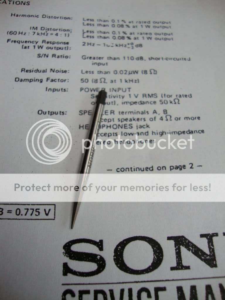
I made a custom made tool to clean the connector leads. It is a old monkey-wrench ( I do not know this is the right name) it is harden steel. It is cut in a triangle shape to scrape the surface of the leads of the connector.

I also cleaned TO3 foot for the V-fet it was polluted with coolant pasta. It would be a catastrophe when the gate would not make contact with the fitting. I also measured the contact resistance after fitting a V-Fet to it, before switching on the new fets.

The tool
DSC00207.jpg
 
Last edited:
Very nice picture sharing! Many thanks for your efforts! I'm confident everything will end up well and you'll have a great setup!
 
After finishing step 2 we can move to the last step and test with the V-fet.

Step 3

To prevent the fets from a possible dead, Piet told me he used resistors in series with the main voltage.

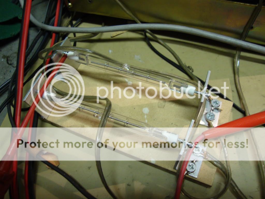
I thought a while, power resistors are expensive. Then I had a idea to use lamp bulbs as power resistor. I bought two Philips 500W halogen lamps for 8 Euro.

The behaviour of a light bulb is like a PTC the resistance can increase 10 times after glowing up. In this case the lamp had a resistance of 7.5Ohm in cold state. And when I shorted the 45+45 Volt with the two lamps in series the current was about 900mA.
Perfect to protect the V-fet.

I used a small piece off MDF and a angled aluminium profile and 12 wood screws to fit the lamps. A nice advantage was that the profile worked like a spring when I screw the lamp between it.
DSC00204.jpg


To start I only fit 1 2sj18 and 1 2sk60 on the left channel to start with.
Then I bais the circuit to 25mV, test the voltage and listen to it.

*note when de potentiometer is in the left corner it is at his minimum value, the 25mV is measured over one 0.33Ohm resistor at the output.


Then I fit the second one on the left channel. Then I bais the left channel to 50mV.

If this works well I repeat this procedure for the right channel.

After fitting all 8 V-fets it was possible to listen to music on the connected speakers, YESS it worked. My occupation is electronics and i have repaired many switching power supplies in my career till now. But it was a bit a gamble to buy this amp and try to buy Nos V-fets in china find replacement transistors. It could turnout in a disaster and loose the investment.

You know what happens when your wife finds out.


Regards, Helmuth
 
Last edited:
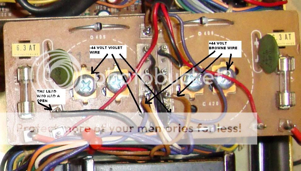
Here a picture of the leads to disconnect so you can put a lamp in series with it.
One lamp in series with the brown wire, and one in series with the violet wire.
(There is also a third violet wire, connected to speaker protection do not disconnect that one other wise the speaker protection switches on.)

The halogen lamp trick works with every end stage repair.

WIRES.jpg


Helmuth wishes you success with repairing.
 
Hi all,

Because the tuner did not have his original feet I mounted new one under the tuner and ampliver.

Not like original 18mm but 22mm high to improve ventilation of the precious V-FET end stage.

pootje.jpg


Regards, Helmuth
 
Great job Helmuth.....what you think of the sound of the amp? I love it!

This amp deserves a sony ST-A7B tuner!

The sound is natural and not aggressive it is has low noise level, for a good impression the J-Fet preamp has to be serviced first new capacitors.

Now I hear a little Hum on the left preamp channel. When I switch on the loudness I hear a little distortion and with the tone control it increases to distort. With the loudness and tone control off it sounds almost clear and still with the little hum.

So there is more to do.

And I am very pleased with the WEGA-tuner, I like it is old fashion with air varicap, and that it is no modern synthesiser tuner.
(I have a nice aiwa synthesiser tuner of end 80ties I bought new then. some thing like the st-a7b)
 
Back
Top Bottom