So here is the first question...
I have seen that KAB and others sell upgraded power supplies for the 1200. I also get the impression that about 90% of the upgrade is simply in getting the transformer (and associated noise) off board. I don't want to spend the money on a new power supply but see no reason not to get mine off board while I have this thing torn apart.
Here you see all of the components as they are originally. The transformer and associated PCB are on the left.
This picture shows the removed transformer, PCB and main board. I would like to get the transformer and PCB into an off board project box. The only rub with this (AFAIK) is that the power switch is at the 120v stage, rather than the 24v or whatever it is stepped down to.
As I see it (please correct me in I'm missing something) I have two options in how to accomplish this.
1. I can put the "On-Off" switch on the project box, and make the switch on the table non-functional. For this I would not use the provided blade switch but an illuminated rocker.
2. I can use the switch exactly as provided.
The advantage I see with option 1 is that I would only need to run three wires from the project box to the table and those wires would be low voltage. The advantage I see with option 2 is that the table will function more closely to original. The downside is that I would have to run six wires and 120 AC into the table. This would obviously limit my options for wire and connectors, and may (I need opinions here) negate some of the benefit of getting the transformer off board.
Two more quick power supply questions...
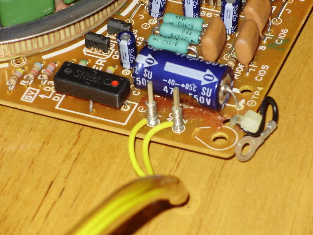
The two yellow wires from the transformer to the main board are (I presume) low voltage. Are they still AC? I'm guessing that they are since they aren't color coded. On this picture you can see that they are connected to the main with several wraps around long binding posts rather than just soldered as most of the connections are. What is the purpose of this? I suspect that knowing why this was done could be important to my decision making.
Also, since all of these components were originally mounted to a common metal plinth, I am thinking that I should run a ground wire from a contact point on each component back to the plinth (that is why I said 3 or 6 wires, not 2 or 5). Am I correct in thinking this? Also, should I use grounded power even though the original design doesn't? It seems to me to be the best option for complete grounding in my system. I suspect that Technics left it off to avoid ground loops in mobile situations, but I certainly could be wrong.
Thanks so much for all of your great advice.