Serious design effort begins on mini-console project

mashaffer

Super Member
I have started seriously looking at the mini-console project I have mentioned before. It is a shrunken stereo console as an iPod dock using 3" FR drivers and an 8" or 10" subwoofer. The main amp will be vacuum tube and the sub will use a plate amp.

The attached document shows some of my early calculations on possible output stage designs. I used Steve Bench's Power and distortion equations to make a spreadsheet and then used enGauge to derive the necessary voltages and currents from the plate curves.

If anyone wants to comment on the chosen operating points I am all ears.

mike
 
Last edited:
Just realized that I made a bunch of errors in those calculations and charts (wrong numbers GIGO). I should always check the next morning I guess. :) Will post corrections when I get a chance to redo it.

mike
 
Cool project! I've been milling around the Bench site trying to come up with better ways of making a fully functional battery powered preamp out of the sub-miniature tubes I have laying around. I'm looking at distortion and operating points the old fashioned way though, plotting load lines using an engineering scale and then breadboarding and playing with voltages to minimize the wrong types of distortion. The FFT screen on the dirt cheap scope I picked up off CL has really helped.

Good luck on the project and keep the pdf updates coming. It's always nice to see how other folks manage the details of a scratch build.
 
It's amazing how well a simple load line and basic distortion calculations work. They do a great job for the tube parameters they're plotted for. The interesting thing for me is how much difference there can be between 2nd, 3rd and higher level distortion based on screen voltage in a simple little battery pentode. Raising the screen by a few volts drastically changes whether the distortion is primarily 2nd order or weird odd harmonics. Triode strapped it's almost all 2nd, just like you would expect.

I'm just learning how to use the scope. I got lucky that a retired Agilent guy decided to post his garage cleaning leftovers right when I logged on.

What full range drivers are you using for the mini? My cabin is solar powered (barely) so I was thinking of bi-amping using tubes for the highs. I should be able to get reasonable run times if I keep the tube amp below 7W.
 
I am using Mark Audio CHR-70 (old version) for the FR. I thought I had a good test amp in an old GE console 6BQ5 I had on hand but it is 8 ohm (CHR-70 is 4 ohm) so the load will not be ideal but should give me an idea of what power level I will need. Right now I am thinking SE UL mode using something in the 6L6 class.

mike
 
Update time

Well I have done a lot of (design) work on this some of which is detailed in this thread.

http://www.audiokarma.org/forums/showthread.php?t=314369

I started that thread to discuss possible OPTs and true to form I caused it to wander far a field in to areas that should be discussed here.

To bring you up to date I have decided that PP 6BQ5 is probably the appropriate topology for this project. The layout is planned to be that of the common Magnavox console layout with forward firing mains (Mark audio CHR-70) and side firing (sub) woofers. The planned power for the subs is a Bash 300W plate amp. The subs will be crossed around 80Hz where the CHR-70s in sealed cabinet naturally rolls off. Since this is the perfect location for a bass control the subwoofer amp gain will be the bass control and a simple treble control included in the mains amplifier.

I played around with transformer input/phase splitting but decided that the tone control would be much easier in this application if I had SE VAS and cathodyne splitter with the treble control between the two stages. I will save the Cinemag transformers that I ordered and use them for the woofer amp in my main stereo system.

The output stage and driver are planned as UL or pentode mode with Schade FB to the driver and no gNFB. The coupling capacitors on the output of the PI are chosen to give 1st order HP at the CHR-70s natural roll off giving nice 3rd order over all crossover.

The plan was to use undersized sealed enclosures for the subs tuned to begin roll off at the desired crossover frequency and then use jFET 2nd order LP at 30Hz to eq. for flat response down to 30Hz.

The resulting schematic looked something like this...

attachment.php


The 12AY7 was chosen for the VAS for low microphonics. You will notice that the treble control consists of a static treble boost followed by a 250K linear pot and shelving resistor for the treble cut portion. I would entertain ideas for a better implementation here but the simulation looks like it can provide adequate performance. Large boost is not really necessary as the control is intended for tweaking not rescuing a junk recording.

The simulated output is thus.

attachment.php


It is not easy to see in this picture but above the subwoofer crossover point the output is flat within about 0.6dB to beyond the limits of hearing. The actual corner frequency for the treble control varies somewhat from boost to cut but not enough to be a deal breaker. There is more cut than boost available but that is not a bad thing either IMO. Still if there are reasonable ways to improve this and still remain passive...

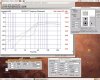
The mains drivers model thusly.

attachment.php


My informal listening tests are consistent with this graph. The red line indicates the max SPL based on 13W of available power. The output for one channel is about 95dB in the pass band which seems adequate for a semi portable system. To increase it significantly would require much more efficient drivers or an unreasonably larger amplifier.

This simulation gives you an idea of the kind of subwoofer setup I had envisioned. This is a 10" Dayton HO sub in an enclosure of about 1/3 ft^3. Note the roll off is almost perfect for the EQ'ed approach. The red line in this graph is not valid as it represents a 600W input whereas I would only be using about 150W per driver so the total output would be less than shown (of course bigger amp could be used but not that big).

attachment.php


But then I discovered the Dayton High Fidelity 8" Sub... This sub goes low enough in a normal sealed enclosure to allow a totally different approach.

attachment.php


Notice that in a 0.8 ft^3 enclosure this one is only down 3dB at 40Hz and only down about 7dB at 30Hz which is as low as I want to really go with this setup due to limited amount of cone area available.

Well this leads to an interesting possibility which simplifies things somewhat

mike

...to be continued...
 

Attachments

  • KMver3.jpg
    KMver3.jpg
    69.6 KB · Views: 888
  • Ver3PutputComp.jpg
    Ver3PutputComp.jpg
    25.7 KB · Views: 886
  • MarkCHR70.jpg
    MarkCHR70.jpg
    95.7 KB · Views: 888
  • Dayton_HO_10.jpg
    Dayton_HO_10.jpg
    93.8 KB · Views: 885
  • DaytonHF8.jpg
    DaytonHF8.jpg
    103.4 KB · Views: 885
Last edited:
OK. Given the subwoofer response above I can skip the eq circuit and attending jFETs entirely. The Bash sub is designed so that you can chose a couple of resistors appropriately and get a slight boost of a few decibels at a selected frequency and a HP to protect the woofers in the process. By choosing the resistors for about 4dB boost at 40Hz I can get nearly flat response down to 30Hz without any additional circuitry.

The Bash has an input impedance of 20K (the schematic below shows 22K as I remembered it wrong when doing the sims but not significant difference). Obviously the 100K pot I had used earlier would require a buffer between the volume control and the sub amp. However I see no reason why I could not use a 10K which is more to the sub amps liking. The 470k load of the tube input will be essentially an open circuit as far as the volume control is concerned. So I reran the simulation using the new pot and sub amp load eliminating the jFETs.

attachment.php


The results seem fine. The output levels didn't really change much. Note I am assuming that the output impedance of the iPod dock or other line level devices that will be used are no more than 1k ohms. If that is not a valid assumption then I may have some problems with output or frequency response.

attachment.php


So am I missing anything? Any suggestions?

mike
 

Attachments

  • KMver4.jpg
    KMver4.jpg
    65.2 KB · Views: 880
  • KMVer4Output.jpg
    KMVer4Output.jpg
    16.7 KB · Views: 875
No comments huh? Either everyone is in awe of my design skills, Bwaaahaahaa, ;) or you are laughing too hard to reply. Seriously any input or criticism would be appreciated before I start ordering parts.

mike
 
Last edited:
No comments huh?

I'm very interested in the outcome of this project. The information you've provided is great but I haven't had the time to really dig through it all. Keep going and keep updating the thread as you make progress. I'll catch up sooner or later.
 
Thanks Scuzzer. Thought you might like to see the chassis I am planning on using.

attachment.php


It is out of an old Hammond Solid State Spinet Organ. Of course the transformer is of no use (I am developing quite a collection of low voltage transformers that are of no particular value. :)) but the size of a proper one will be similar. I will remove the two can caps and use those locations for a new can cap and the rectifier socket if I go with a tube rectifier. After removing the heat sink and circuit board the remaining real estate should be about perfect for the four power tubes and four dual triodes.

I will probably mount all of the controls on a remote panel and put the chassis down inside the cabinet in a cooling plenum such that air is drawn in the bottom and exhausted out the top rear by convection.

mike
 

Attachments

  • HammondChassis.jpg
    HammondChassis.jpg
    106.8 KB · Views: 836
OK. I have stripped the chassis. It turns out that I have a PT of the right physical size. It fits the cut out perfectly except that the bolt holes need to be slightly closer to the bell so I would have to extend the holes into slots. Unfortunately the current capability may be coming up short.

The power tubes will be idling at 40mA each (160mA) and there will be about 20 or 25mA more for the preamp tubes for a total of 185mA or so.

The transformer is a surplus from JudyBox guitar amps prototypes.

attachment.php


It has a 320V/150mA winding with a tap at 265V and a 45V tap (on one side) for bias supply. I would be using the 265V B+ and SS rectification to get around 300V and would not be using the 5V winding at all so I would probably be alright WRT to total VA but I would be busting the B+ current rating by over 20%.

I may try it anyway just to see what happens but I am not sure it is a good idea to run that hard in an enclosed system. Any thoughts on that?

Here is the stripped chassis.

attachment.php


attachment.php


Will remove those brackets. Those lug strips will come in very handy. I will have to ponder a bit to figure out the best socket layout. I can use the 9 pin octal sized socket to connect an umbilical to the control panel.

I could put the output tube sockets where the can caps were and put caps underneath but I kind of like the idea of using a CE can cap for the PS filter.

mike
 

Attachments

  • StrippedChassisTop.jpg
    StrippedChassisTop.jpg
    80.2 KB · Views: 798
  • StrippedChassisUnder.jpg
    StrippedChassisUnder.jpg
    108 KB · Views: 799
  • JudyBoxWithHeaterCurrent.jpg
    JudyBoxWithHeaterCurrent.jpg
    85 KB · Views: 798
Well true to form I am looking at going a little different direction. I am still planning on a separate preamp section to do the volume control and tone control but I am back to thinking transformer input to the power amp section. I have done some preliminary design on a PP triode amp using 6EM7 that indicates that I should be able to get about 9 or 10 WPC with no need for FB or any fancy footwork. Here is a peak at the power section I have in mind.

attachment.php


The models are Koren style created with paint_kit curve matching software. The models seem to match the paper calculations pretty well. The preamp tube was actually the hardest to get a match but I got fair matching in the region most likely to matter I think.

Note I think I screwed up on that transformer model as that looks like 2K ish load and I think something closer to 8k would be more appropriate so might not make quite 10W but others seem to have reached about that point so...

Output just before the onset of clipping looks like this (actually you can just see the star of it on the bottom lobes).

attachment.php


FR looks like this.

attachment.php


When driven into clipping I get a pretty hard clip due to grid current.

attachment.php


Though I don't have a picture of the results I did try putting a CF before the output tube grids and the overload characteristics were dramatically improved. I even got a couple more watts out of it before the distortion became visible in the output waveform. The results were so dramatic that I am seriously considering doing it even though space and heat are an issue in this case. I may have to bite the bullet and try those static sensitive little MOSFETs as a source follower. :)

I also looked at VAS ==> Cathodyne but the transformer input version was so much less sensitive to minor bias changes and was much better about balanced overload that I see no reason to even consider that approach especially since I now have some CineMag trannies in my hot little (OK, not so little) hands.

mike

Sorry fpr the big pics. Forgot to reduce.
 

Attachments

  • 6EM7_transin_Schem.png
    6EM7_transin_Schem.png
    28.8 KB · Views: 782
  • 6EM7_transin_out.png
    6EM7_transin_out.png
    21.8 KB · Views: 780
  • 6EM7_transin_HardClipping.png
    6EM7_transin_HardClipping.png
    15 KB · Views: 776
  • 6EM7_transin_FR.png
    6EM7_transin_FR.png
    16.1 KB · Views: 775
...

The attached document shows some of my early calculations on possible output stage designs. I used Steve Bench's Power and distortion equations to make a spreadsheet and then used enGauge to derive the necessary voltages and currents from the plate curves.

Just looked at the application you mentioned, enGauge. That is absolutely cool.

Thanks for the post.

Cool project too.
 
I'm sorry to post off topic but would you mind sharing which software package you use for your simulations? I have Multi_Sim but have not yet been able to create a device (i.e. tube) for simulation.

Thank you

Shelly_D
 
I like the second schematic much better , what is the input transformers and output transformers you are going to use . I have a couple pair of UTC A-18's and concidered building something similar with 6SL7's and 6B4G's .The only thing i would sugest is using .1 uf coupling caps instead of .68 uf ..
 
I'm also a multi-sim user, and have had a hard time finding good vacuum tube models.

And, just to clear it up, I'm not laughing, I'm in awe.:ntwrthy:
 
I will probably use Edcor OPTs. The input trannies I plan to use are CineMag CM-29111. They are a new one based on the CM-2436. Yeah, on the coupling caps I admit that I just tossed in something big so I wouldn't have to fuss with it.

I tried changing the inductances on the OPT model to what I think should be 8k and the simulation won't go above 5V peak at the output and rather distorted at that. So I have some more work to do as my hand calculations tell me that I should do much closer to 10W before serious distortion sets in. Maybe I don't understand how to model the tranny right (or possibly my tube models aren't as good as I thought).

mike
 
BTW the revised OPT model that causes the crappy results is 250H for each primary side and 0.5H for the secondary which is loaded with 4 ohm resistor. My math is as such...

250*4 = 1000 total primary inductance P-P.

Imp ratio = Lpri/Lsec = 1000/.5 = 2000.

Zpri = Imp ratio times load = 4*2000 = 8K.

Correct?

Tomorrow I will try to post my graphical analysis to see if I have screwed up there.

mike
 
Back
Top Bottom