SX-1980 Recap Assistance

bbauer01

Active Member
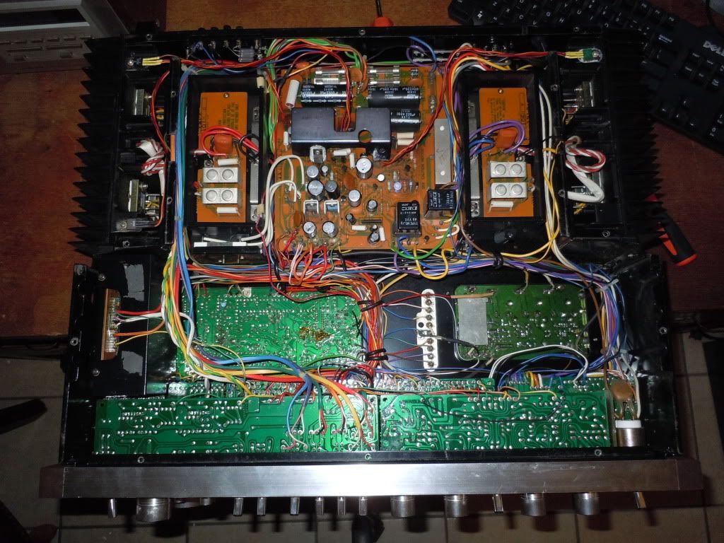
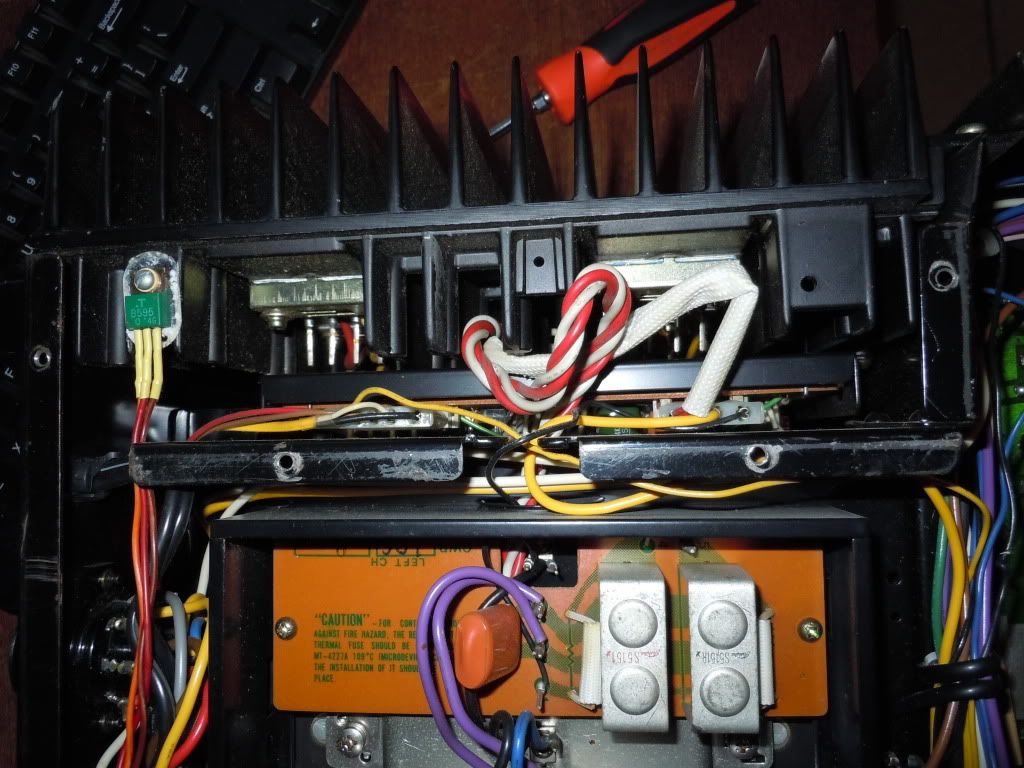
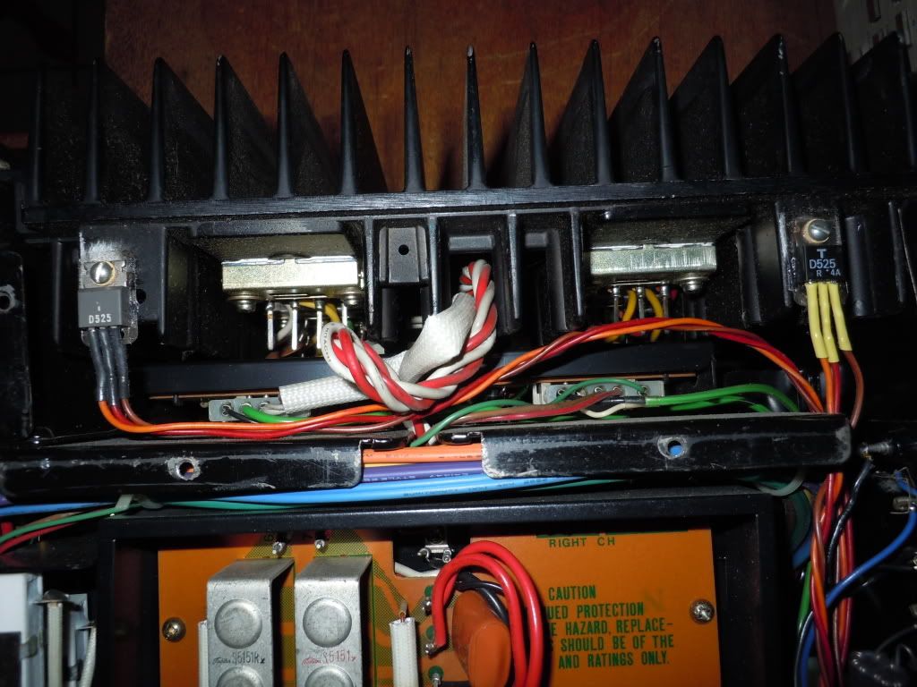
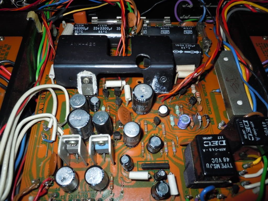
I have decided that it is time to recap my SX-1980. I did some searching and it doesn't look like anyone put together a recap list for this unit. My service manual lists all the caps with the exception of one board. (unless I am missing something) If I compile a list in spreadsheet forum would Mark or someone else knowledgeable be able to assist me with best choice and available replacements?
 
You should check each board individually as well, you will be taking them all apart to recap them anyway.
 
The list shows the cap values that I removed. You'll need a bit of technical knowledge to decide what caps to replace them with.
Look at the pictures and read that and other similar threads to get an idea what caps people like to use. Personally I like the Nichicon FG series for audio circuits.
 
The experience level of those attempting to work inside the SX-1980 is dropping dangerously low. The 1980 almost invariably needs additional work besides caps. The needs vary, none is ever quite the same. It is a powerful but finicky beast.

This (in general) is leading somewhere bad....

I was wondering just how long it was going to take for someone (else) to notice that the downloadable SX-1980 service manuals (that I have been able to find) are incomplete, and comment upon it.
 
Last edited:
I reviewed the previous threads regarding the SX-1980. I think in spreadsheet terms, so I made a spreadsheet and pasted the contents here. I cross referenced everything to Mouser part numbers. The list isn't 100% complete, but it is a starting point.


Power Supply
AWR-154 c203 3300 35 ach 647-TVX1H332MDD 3300 50
AWR-154 c204 220 160 ach 647-TVX2C221MDD 220 160
AWR-154 c205 220 160 ach 647-TVX2C221MDD 220 160
AWR-154 c210 100 10 cea 647-UPW1A101MDD 100 10
AWR-154 c211 100 16 cea 647-UPW1V101MPD 100 35
AWR-154 c212 100 10 cea 647-UPW1V101MPD 100 35
AWR-154 c213 100 6 cea 647-UPW1V101MPD 100 35
AWR-154 c216 100 50 cea 647-UPW1H101MPD 100 50
AWR-154 c217 100 50 cea 647-UPW1H101MPD 100 50
AWR-154 c218 10 50 cea 647-UPW1H100MDD6 10 50
AWR-154 c219 10 50 cea 647-UPW1H100MDD6 10 50
AWR-154 c220 100 100 cea 647-UPW2A101MHD 100 100
AWR-154 c221 100 100 cea 647-UPW2A101MHD 100 100
AWR-154 c222 100 50 cea 647-UPW1H101MPD 100 50
AWR-154 c223 100 50 cea 647-UPW1H101MPD 100 50
AWR-154 c224 100 50 cea 647-UPW1H101MPD 100 50
AWR-154 c225 100 50 cea 647-UPW1H101MPD 100 50
AWR-154 c301 100 16 cea 647-UPW1V101MPD 100 35
AWR-154 c302 100 16 cea 647-UPW1V101MPD 100 35
AWR-154 c303 47 16 cea 647-UPW1C470MDD 47 16
AWR-154 c305 10 16 cea 647-UPW1V100MDD 10 35


Tuner
AWE-093 c10 0.1 35 csza 598-DSF050J 0.1 50
AWE-093 c16 2.2 50 cea 647-UPW1H2R2MDD 2.2 50
AWE-093 c19 100 6 cea 647-UPW1A101MDD 100 10
AWE-093 c20 1 50 cea 647-UPW1H010MDD 1 50
AWE-093 c22 33 25 ceanl 647-UKL1E330MEDANA 33 25
AWE-093 c23 33 25 ceanl 647-UKL1E330MEDANA 33 25
AWE-093 c24 22 16 cea 647-UPW1H220MDD 22 50
AWE-093 c28 6.8 6 csza 647-UKL1E6R8KDDANA 6.8 25
AWE-093 c29 1 25 csza 598-DSF050J105 1 50
AWE-093 c30 1 25 csza 598-DSF050J105 1 50
AWE-093 c31 1 50 cea 647-UPW1H010MDD1TD 1 50
AWE-093 c32 100 16 cea 647-UPW1V101MPD 100 35
AWE-093 c33 10 16 ceanl 647-UKL1V100KDD1TA 10 35
AWE-093 c34 10 16 ceanl 647-UKL1V100KDD1TA 10 35
AWE-093 c37 100 16 cea 647-UPW1V101MPD 100 35
AWE-093 c38 0.56 35 csza 598-DSF050J564 0.56 50
AWE-093 c39 0.56 35 csza 598-DSF050J564 0.56 50
AWE-093 c40 220 16 cea 647-UPW1V221MPD 220 35
AWE-093 c41 10 16 cea 647-UPW1V100MDD 10 35
AWE-093 c42 33 16 cea 647-UPW1H330MED 33 50
AWE-093 c43 10 16 ceanl 647-UKL1V100KDD1TA 10 35
AWE-093 c44 10 16 cea 647-UPW1V100MDD 10 35
AWE-093 c45 47 10 cea 647-UPW1A470MDD6 47 10
AWE-093 c46 10 16 cea 647-UPW1V100MDD 10 35
AWE-093 c47 47 10 cea 647-UPW1A470MDD6 47 10
AWE-093 c55 10 16 cea 647-UPW1V100MDD 10 35
AWE-093 c57 1 50 cea 647-UPW1H010MDD 1 50
AWE-093 c61 0.22 35 csza 598-DSF050J224 0.22 50
AWE-093 c62 0.1 35 csza 598-DSF050J 0.1 50
AWE-093 c63 10 16 cea 647-UPW1V100MDD 10 35
AWE-093 c64 1 25 csza 598-DSF050J105 1 50
AWE-093 c65 0.47 35 csza 598-DSF050J474 0.47 50
AWE-093 c66 2.2 16 csza 647-UKL1H2R2KDDANA 2.2 50
AWE-093 c68 4.7 16 csza 647-UKL1E4R7KDDANA 4.7 35
AWE-093 c69 10 16 cea 647-UPW1V100MDD 10 35
AWE-093 c70 2.2 16 csza 647-UKL1H2R2KDDANA 2.2 50
AWE-093 c71 100 16 cea 647-UPW1V101MPD 100 35
AWE-093 c72 100 16 cea 647-UPW1V101MPD 100 35
AWE-093 c74 22 16 cea 647-UPW1H220MDD 22 50
AWE-093 c76 4.7 35 cea 647-UPW1V4R7MDD 4.7 35
AWE-093 c77 3.3 50 cea 647-UPW1H3R3MDD 3.3 50
AWE-093 c79 10 16 cea 647-UPW1V100MDD 10 35
AWE-093 c83 0.1 35 csza 598-DSF050J 0.1 50
AWE-093 c87 10 16 cea 647-UPW1V100MDD 10 35
AWE-093 c88 100 16 cea 647-UPW1V101MPD 100 35
AWE-093 c90 100 16 cea 647-UPW1V101MPD 100 35


APC Assembly
AWX-124 c4 47 16 cea 647-UPW1E470MDD 47 25
AWX-124 c5 100 16 cea 647-UPW1V101MPD 100 35
AWX-124 c8 2.2 25 csza 647-UKL1H2R2KDDANA 2.2 50
AWX-124 c12 100 6 cea 647-UPW0J101MDD 100 6.3


EQ Amp (phono)
AWF-030 c1 2.2 50 ceanl 647-UKL1H2R2MDAANA 2.2 50
AWF-030 c2 2.2 50 ceanl 647-UKL1H2R2MDAANA 2.2 50
AWF-030 c11 2200 10 cea 647-UPW1A222MPD6 2200 10
AWF-030 c12 2200 10 cea 647-UPW1A222MPD6 2200 10
AWF-030 c19 220 6 cea 647-UPW1A221MED 220 10
AWF-030 c20 220 6 cea 647-UPW1A221MED 220 10
AWF-030 c23 220 35 cea 647-UPW1V221MPD 220 35
AWF-030 c24 220 35 cea 647-UPW1V221MPD 220 35
AWF-030 c27 10 50 ceanl 647-UKL1H100MDDANA 10 50
AWF-030 c28 10 50 ceanl 647-UKL1H100MDDANA 10 50
AWF-030 c29 10 50 ceanl 647-UKL1H100MDDANA 10 50
AWF-030 c30 10 50 ceanl 647-UKL1H100MDDANA 10 50
AWF-030 c31 220 35 cea 647-UPW1V221MPD 220 35
AWF-030 c32 220 35 cea 647-UPW1V221MPD 220 35


Function Switch
GWS-129 c1 220 6 cea 647-UPW1A221MED 220 10


APC Control
GWM-104 c3 33 10 csza 647-UKL1E330MEDANA 33 25


EDIT... cap list compiled for board AWG-058 which is missing from most online service manuals.

Flat AMP AWG-058
AWG-058 c5 4.7 50 ceanl 647-UKL1H4R7KDDANA 4.7 50
AWG-058 c6 4.7 50 ceanl 647-UKL1H4R7KDDANA 4.7 50
AWG-058 c7 10 16 cea 647-UPW1V100MDD 10 35
AWG-058 c8 10 16 cea 647-UPW1V100MDD 10 35
AWG-058 c9 10 16 cea 647-UPW1V100MDD 10 35
AWG-058 c10 10 16 cea 647-UPW1V100MDD 10 35
AWG-058 c11 330 35 cea 647-UPW1V331MPD6 330 35
AWG-058 c12 330 35 cea 647-UPW1V331MPD6 330 35


Tone Control
AWG-059 c1 4.7 25 csza 647-UKL1H4R7KDDANA 4.7 50
AWG-059 c2 4.7 25 csza 647-UKL1H4R7KDDANA 4.7 50
AWG-059 c3 4.7 25 csza 647-UKL1H4R7KDDANA 4.7 50
AWG-059 c4 4.7 25 csza 647-UKL1H4R7KDDANA 4.7 50
AWG-059 c11 2.2 50 ceanl 647-UKL1H2R2MDAANA 2.2 50
AWG-059 c12 2.2 50 ceanl 647-UKL1H2R2MDAANA 2.2 50
AWG-059 c13 2.2 50 ceanl 647-UKL1H2R2MDAANA 2.2 50
AWG-059 c14 2.2 50 ceanl 647-UKL1H2R2MDAANA 2.2 50
AWG-059 c17 100 10 ach 647-UPW1A101MDD 100 10
AWG-059 c18 100 10 ach 647-UPW1A101MDD 100 10
AWG-059 c19 2.2 50 ceanl 647-UKL1H2R2MDAANA 2.2 50
AWG-059 c20 2.2 50 ceanl 647-UKL1H2R2MDAANA 2.2 50
AWG-059 c27 2.2 50 ceanl 647-UKL1H2R2MDAANA 2.2 50
AWG-059 c28 2.2 50 ceanl 647-UKL1H2R2MDAANA 2.2 50
AWG-059 c29 2.2 50 ceanl 647-UKL1H2R2MDAANA 2.2 50
AWG-059 c30 2.2 50 ceanl 647-UKL1H2R2MDAANA 2.2 50
AWG-059 c33 100 10 ach 647-UPW1A101MDD 100 10
AWG-059 c34 100 10 ach 647-UPW1A101MDD 100 10
AWG-059 c35 2.2 50 ceanl 647-UKL1H2R2MDAANA 2.2 50
AWG-059 c36 2.2 50 ceanl 647-UKL1H2R2MDAANA 2.2 50
AWG-059 c37 100 16 ach 647-UPW1V101MPD 100 35
AWG-059 c38 100 16 ach 647-UPW1V101MPD 100 35
AWG-059 c39 100 16 ach 647-UPW1V101MPD 100 35
AWG-059 c40 100 16 ach 647-UPW1V101MPD 100 35
AWG-059 c43 10 25 csza 647-UKL1H100KDDANA 10 50
AWG-059 c44 10 25 csza 647-UKL1H100KDDANA 10 50


Filter Assembly
AWM-119 c1 0.22 35 csza 598-DSF050J224 0.22 50
AWM-119 c2 0.22 35 csza 598-DSF050J224 0.22 50
AWM-119 c3 0.22 35 csza 598-DSF050J224 0.22 50
AWM-119 c4 0.22 35 csza 598-DSF050J224 0.22 50
AWM-119 c5 4.7 25 csza 647-UKL1H4R7KDDANA 4.7 50
AWM-119 c6 4.7 25 csza 647-UKL1H4R7KDDANA 4.7 50
AWM-119 c11 10 25 csza 647-UKL1H100KDDANA 10 50
AWM-119 c12 10 25 csza 647-UKL1H100KDDANA 10 50


Power Amp – L
GWH-109 c1 100 100 cea 647-UPW2A101MHD 100 100
GWH-109 c3 100 100 cea 647-UPW2A101MHD 100 100
GWH-109 c35 0.22 25 cssa 598-DSF050J224 0.22 50


Power Amp – R
GWH-110 c2 100 100 cea 647-UPW2A101MHD 100 100
GWH-110 c4 100 100 cea 647-UPW2A101MHD 100 100
GWH-110 c36 0.22 25 cssa 598-DSF050J224 0.22 50


Power Meter
AWM-122 c1 0.47 35 csza 598-DSF050J474 0.47 50
AWM-122 c2 0.47 35 csza 598-DSF050J474 0.47 50
AWM-122 c3 220 6 cea 647-UPW1A221MED 220 10
AWM-122 c4 220 6 cea 647-UPW1A221MED 220 10
 
Last edited:
The experience level of those attempting to work inside the SX-1980 is dropping dangerously low. The 1980 almost invariably needs additional work besides caps. The needs vary, none is ever quite the same. It is a powerful but finicky beast.

This (in general) is leading somewhere bad....

I was wondering just how long it was going to take for someone (else) to notice that the downloadable SX-1980 service manuals (that I have been able to find) are incomplete, and comment upon it.

From previous readings, I assume you are primarily concerned with the power supply board on these units, since they are prone to heat / failure. You have commented before about replacing the TO-220's on the power supply board with mje15032/33's. This will be addressed.

I also read about EchoWars 'current source' modification. Would this be a wise modification to pursue at this time?
 
Last edited:
I PM'ed EW about that. He said that if it works leave it be. His fix was intended as an option for those that had to replace the unobtainable FET.
Replace the 35 volt zener diodes with a pair of 17v and 18v 1/2 watt zeners in series - apparently that addresses a known frailty in that area.
The PS PCB traces are quite fragile - proceed with caution.
 
I PM'ed EW about that. He said that if it works leave it be. His fix was intended as an option for those that had to replace the unobtainable FET.
The PS PCB traces are quite fragile - proceed with caution.

Thank you. You saved me from having to bother EW and asking the same thing. This unit currently functions, so I will leave out the 'current source' modification.

Regarding the frail traces ... my sx-1280 power supply board was really cooked and I had to deal with the same thing. In fact, as far as signs of (over)heating, board AXW-154 on my 1980 doesn't look near as bad as the power supply board in my sx-1280 did when I repaired and recapped it.
 
I PM'ed EW about that. He said that if it works leave it be. His fix was intended as an option for those that had to replace the unobtainable FET.
I'll clarify a bit...I strongly suspect that the original Pioneer parts were selected for higher voltage, something that is not really an option for you and I. Although the FET's are somewhat fragile in this application, as long as the four 24V zeners (D208~D211) and the two 100 ohm resistors (R211 & R213) are in good shape, the FET's should be protected. Consider that thus far they have made it 30+ years.
 
It also appears that previous repairs have been done... Notice the devices mounted on the output heatsinks.

DSCN0146.jpg


DSCN0149.jpg


DSCN0148.jpg


DSCN0150.jpg
 
Last edited:
Interesting pictures. Kind of neat the way they dispersed the heat generating components.
Mine has 2 cut traces with resistors inserted feeding the aforementioned FETs.
It appears that the SX-1980 had a known weakness in the power supply area and there were a variety of home grown and factory fixes to address it.

Mine has a cut trace and a resistor on the foil side. I swore it didn't look this bad last year when I bought the unit and did my initial cleanup and deoxit. I guess I didn't pay close enough attention. I will post a picture of the backside of the board and detail the exact location of the cut trace and resistor.

Should I leave these modifications intact, or should this be dealt with in another manner?
 
Last edited:
Oh, I don't think it looks bad at all - just unique to my experiences. Of course I've only been inside (or for that matter seen) only one SX-1980 - and that one's mine.
I'd be interested in seeing a picture of the underside of your PS PCB to see if the mod is the same as mine. The resistors are 470Ω.

Judging by the heat damage by the screw on the underside of the PCB I'm thinking it would be a good move to relocate the 2 transistors as on yours.


attachment.php
 
w1jim: from reading your thread it doesn't look like you touched anything on the power supply board other than the capacitors. Is that correct?

I am debating if the board should be re-done or left alone. I want this unit to be as bullet-proof as possible, so my inclination is to do as much as possible. But the other side of me feels like it is working, so why touch it...

I know that MTF has stated before to replace all the TO-92s with:

522-ZTX795A PNP TO-92E ebc 140v 0.5a 1.5w 100mhz 100-800hfe
522-ZTX694B NPN TO-92E ebc 120v 0.5a 1.5w 130mhz 150-500hfe

and the TO-220s with
On-Semi MJ15032 / MJ15033

and replace the 35v zener diodes with a set of 1/2W 17V and 18V zeners

I know for certain that my caps have seen some heat from looking the stretched plastic covers.
 
w1jim: from reading your thread it doesn't look like you touched anything on the power supply board other than the capacitors. Is that correct?
Yes, this is correct.
IMHO I would not change the positioning of the transistors on yours nor would I update the TO-92 parts. Updating the zeners would help in your goal of making it bulletproof but I don't know that I'd replace the TO-220 parts with the OnSemis - that's a toss up given how they've been relocated.
I'm guessing that these failed at some point and were replaced and relocated. They'll get significantly less stress at the current location. But then if you're in there why not spend the extra $3?

My feeling is that previously the larger heatsink on the PCB had the 2 - TO-220 parts sharing it's ability to dissipate the heat and the third TO-220 which was adjacent on the smaller heatsink was also heating that area. Things were getting plenty hot in a poorly ventilated area. By relocating the 2 transistors now a significant amount of heat has been removed from that area and the remaining TO-220 has it's very own private heat sink.

I have those 2 OnSemi transistors but don't yet have the 17V & 18V zeners (they're on the list for when I next need to order stuff). Once those come in I'm seriously considering relocating the TO-220s to the way yours are.
 
Wow... some crimes have been committed here. Notice the missing components and the rig-job. Diode d210, d211 are missing. Notice the lack of the one 2sk34 fet (q207). Capacitor (c229...I think, my service manual isn't very hi-res, I am going to buy a good one tonight) is missing.

w1jim: the resistor on the back of mine is also 470ohm

DSCN0157.jpg


DSCN0158.jpg


DSCN0162.jpg


DSCN0163.jpg
 
Last edited:
i know some boards have "places" for components which are not used. definitely find out though since someone has been in it previously. odd that a resistor is hanging out on the bottom. was the tech stoned when he installed it?
 
Back
Top Bottom