• The move to the new server is done. There are some software and database maintenance updates in process. This has us passing the hat around to help out. We appreciate any donations. Seriously, even a dollar helps. The payment page may be found here - https://www.audiokarma.org/support.html

NTC-resistor value in Marantz 4230

A-zon

New Member
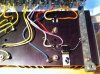
Hi, my first post here, and it is about the value of the NTC resistor mounted at the heatsink next to the output transistors, cant`t find it in part index in the servicemanual for the 4230, anybody knows the proper value and can tell me. I have different values at measuring them, the most truly is around 2 kohm,
can that be right?
013.jpg
012.jpg
 
Register to hide this ad
H005 and H006 are SV-03 bias diodes with a VF of 1.6 to 2.0V at 1ma If. Consolidated Electronics probably has them or 3-1N4148 diodes in series should work.

Tom
 
Thanks for the quick reply Tom, and for showing me the right way to go here in this slow going project with a burned out amp-section, soon as possible I will update this.
 
Hi Tom, thanks for the links, very informative.I have a god FLUKE meter with diod test, I´m planing to bye 12 new diods in that value you suggested, stack them toghether 3 and 3 in series and change all 4 out. One thing I don´t understand is; why are this diods mounted on the heatsink like a heatsensitive resistor? The answer will just show how little I now, I think.
 
Some meters don't have enough voltage to forward bias 3 junctions into conduction, my new Fluke does, my old one doesn't.

As transistors get hotter, their DC current gain increases, which causes more current to flow which causes them to get hotter...see where this is going? The diode, in thermal contact with the heat sink, is used to reduce the idle current as things heat up.

Tom
 
Thanks for bringing light over this, now I understand the importance with a proper thermal contact between these diods and the heat sink. My first thought is to stack the diods flat in shrink tubing and flat out the old clamp for a better fit.
 
Rather than sit and contemplate ways to replace it, I'd ponder ways to properly check the one you have. A 9V battery and a 500 ohm resistor to limit current would work...wire it up and measure the voltage across the diode. If it is good, with the battery wired so that the diode conducts, you should read something like 2V across the diode. Reverse the battery, and the whole 9V from the battery will be across it.
 
Two out of four of these diods are not longer usable because at one the plastic is cracked and leg broken, at the other one leg is broken upclose the plastic and not usable. With tips from you EW I noted the cracked diod failured, there where some tiny bit sticking out from the plastic where I found contact, that one was mounted on the smoked side. There are no soldering space at the other, sadly because it`s OK.
Sorry that I don`t mentioned that from the start.
 
Hi!
Another one Marantz is back. And that is with help from Catrafter and Echowars. Thanks for tips and tricks guys. :thmbsp: I also recap and mounted LED`s. But for one thing I`m a little concerned: I can`t set bias voltage down to 15 mVdc it`s around 80 mV and the trimpot is so mutch to it`s end/start as it can be, voltage output from the voltage regulator is set to 35v.
Maybe 4 insted of 3 diods in series could do it?
How important is a correct 15 mVdc bias set?


http://www.audiokarma.org/forums/attachment.php?attachmentid=281537&stc=1&d=1308350275
http://www.audiokarma.org/forums/at...nt.php?attachmentid=281539&stc=1&d=1308350275

http://www.audiokarma.org/forums/at...nt.php?attachmentid=281541&stc=1&d=1308350275
 

Attachments

  • 5.jpg
    5.jpg
    64.6 KB · Views: 56
  • 4.jpg
    4.jpg
    78.1 KB · Views: 82
  • 3.jpg
    3.jpg
    69.3 KB · Views: 71
  • 2.jpg
    2.jpg
    59.8 KB · Views: 89
  • 1.jpg
    1.jpg
    110.6 KB · Views: 87
The pic of the front looks great!
The bias is very important. 80mV across 1 Ohm = 80mA, way too much. Your output transistors are going to run hot. What is the voltage drop across the diode stacks you built?

Tom
 
After 30 minutes whitout a signal input I measured 2v across the diods and 90 Fahrenheit direct on the output transistors.
 
I'm finding conflicting data on the SV-3 diodes, perhaps two 1N4148s in series would be a better substitute.

Tom
 
Thanks for taking time Tom. Just looked at Mouser and they don`t have that diod that ends with an "s" you suggested, googled it and theres only datasheet coming up. Some kind of high speed diod? Where to find?
 
Tom mentions 1N4148 diodes - to indicate more than one he placed an 's' at the end of the diode type number - the 's' isn't part of the type number.

Like this,

One 1N4148 OR Two 1N4148s in series (perhaps this should have been written - 1N4148's - )

Just punctuation - nothing more

Carry on....
 
Happy end in my corner!
I did what you suggested whith the diods in your last reply Catrafter, now it meassure correct bias voltage, many thanks, you are the man. :yes:
It sounds and look very good, not a scratch at the face, only the "R" in "Rear" besides the phoneplug are gone, I can live with that.
Enjoy the pictures.

Regards from Sweden
//Roland
 

Attachments

  • 1.jpg
    1.jpg
    60.4 KB · Views: 41
  • 2.jpg
    2.jpg
    71.2 KB · Views: 31
  • 3.jpg
    3.jpg
    77.7 KB · Views: 42
  • 4.jpg
    4.jpg
    71.9 KB · Views: 34
  • 5.jpg
    5.jpg
    91.6 KB · Views: 58
  • 6.jpg
    6.jpg
    116.9 KB · Views: 51
Sorry about the mix up on the number of diodes. I should have looked at the schematic instead of just the data sheet on the bias diode.
I'm glad it all worked out in the end, that IS a beauty. You did a great job.

Tom
 
The stock diode is an SV-3A, so the implication there is that the original is a three junction diode. If one of the originals is functional, you should measure its Vf voltage. The diode replacement is a last resort, as the original is there to modulate the bias current as temp rises and replacement with a series diode string may leave the amp severely under or over compensated.

These 'SV' and STV' multijunction diodes are NOT prone to failure...I've worked on amps where damn near every component on the board was fried to a crisp, but the mj-diodes were fine. So when I see a thread where someone is looking for a replacement, a red flag comes up and I have to ask 'what is the problem with the original? Why do you think it is bad?'
 
Back
Top Bottom