

I found a nice schematic for a LED replacement for the neon
strobe lamp for Dual turntables, posted by dualfred on dual-board.de
The lamp on my TT started failing, and I found this works great.

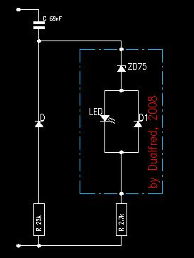
The schematic for the dual strobe is below. The LED lamp is the part shown in the box here -
I wrote up a little howto to help you make your own LED lamp.
Before you go any further, note that the strobe board has potentially
lethal line level voltages. Proceed at your own risk.
If you don't know what you are doing, and kill yourself, don't come back to haunt me or
this board")
Here's what you will need:
* A small piece of bare copper clad PCB, size 6mm x 26mm (1/4" x 1 1/16")
Double sided board is ok, but make sure to cut the copper
continuity on the reverse side.
* Two super bright surface mount LEDs, as per your choice of color.
5mm through hole LEDs are too tall to fit into the Dual strobe box,
so I had to salvage a couple of SMD LEDs from a broken torch.
White LEDs are working fine, though I may change them to orange
later.
* One Diode - 1N4004, 1N4007 or similar
* One Zener diode - 75V, 1 watt (1N4761)
I had a 68V, 1W (1N4760) on hand, and it works fine for me, so
there is some tolerance here, if you don't have the exact value.
* Two faston PCB type terminals
* The usual diyers tools - soldering iron, clippers, dremel...
Let's get started -
1) Using a dremel or a xacto knife, cut the copper (on both sides,
if you are using double side board) of the PCB as shown.
2) Solder the two LEDs. I used a PLCC-2 type LED. The cathode is
marked by a notch on the package. Both LEDs are in parallel, so
the cathodes go the same way.

3) Solder the 1N4004 diode as shown, anti-parallel to the LEDs.
This is to protect the LEDs from high reverse voltage. Note
where the banded end goes, as in the pic.
4) Solder the zener diode as shown. The zener helps to get a
sharp pulse of light. Again, note the orientation of the banded end.
For the metal tabs at the end, I dremeled them out of
a couple of faston PCB terminals and soldered them to the ends
of the LED lamp PCB
Now, your LED lamp is ready, and should look like the one in
the pic in this listing (have a limit of 6 pics, hence the reference) -
http://cgi.ebay.de/Ersatz-Dual-Stroboskop-Glimmlampe-LED-Typ-orange-/270746598643
To get more brightness, I replaced the 0.068uf cap on the
Dual Strobe PCB with a 0.1uf, 400V AC rated cap, and also
changed the 2.7K resistor to a 1Kohm, 1/2 watt one.
In case you are wondering why the pics look a little wierd, it's because I forgot to take pics
while making the lamp, so had to create these pics using an image editing tool.
strobe lamp for Dual turntables, posted by dualfred on dual-board.de
The lamp on my TT started failing, and I found this works great.
The schematic for the dual strobe is below. The LED lamp is the part shown in the box here -
I wrote up a little howto to help you make your own LED lamp.
Before you go any further, note that the strobe board has potentially
lethal line level voltages. Proceed at your own risk.
If you don't know what you are doing, and kill yourself, don't come back to haunt me or
this board
Here's what you will need:
* A small piece of bare copper clad PCB, size 6mm x 26mm (1/4" x 1 1/16")
Double sided board is ok, but make sure to cut the copper
continuity on the reverse side.
* Two super bright surface mount LEDs, as per your choice of color.
5mm through hole LEDs are too tall to fit into the Dual strobe box,
so I had to salvage a couple of SMD LEDs from a broken torch.
White LEDs are working fine, though I may change them to orange
later.
* One Diode - 1N4004, 1N4007 or similar
* One Zener diode - 75V, 1 watt (1N4761)
I had a 68V, 1W (1N4760) on hand, and it works fine for me, so
there is some tolerance here, if you don't have the exact value.
* Two faston PCB type terminals
* The usual diyers tools - soldering iron, clippers, dremel...
Let's get started -
1) Using a dremel or a xacto knife, cut the copper (on both sides,
if you are using double side board) of the PCB as shown.
2) Solder the two LEDs. I used a PLCC-2 type LED. The cathode is
marked by a notch on the package. Both LEDs are in parallel, so
the cathodes go the same way.
3) Solder the 1N4004 diode as shown, anti-parallel to the LEDs.
This is to protect the LEDs from high reverse voltage. Note
where the banded end goes, as in the pic.
4) Solder the zener diode as shown. The zener helps to get a
sharp pulse of light. Again, note the orientation of the banded end.
For the metal tabs at the end, I dremeled them out of
a couple of faston PCB terminals and soldered them to the ends
of the LED lamp PCB
Now, your LED lamp is ready, and should look like the one in
the pic in this listing (have a limit of 6 pics, hence the reference) -
http://cgi.ebay.de/Ersatz-Dual-Stroboskop-Glimmlampe-LED-Typ-orange-/270746598643
To get more brightness, I replaced the 0.068uf cap on the
Dual Strobe PCB with a 0.1uf, 400V AC rated cap, and also
changed the 2.7K resistor to a 1Kohm, 1/2 watt one.
In case you are wondering why the pics look a little wierd, it's because I forgot to take pics
while making the lamp, so had to create these pics using an image editing tool.
Attachments

Last edited:


