


First up if you have read my reviews of my PhonoClone 3 phono stage you know how good I feel it is. IMO it's one of the best phono stages out there and I'm talking about stages costing thousands.
Here's the good part for DIY'ers you can easily build one of these moving coil only phono stages yourself and embarrass your friends high end phono stages, that's until they build one too .
.
For very little money you can hear your vinyl the way you never thought possible, enough chit chat for now here's how to do it in three easy steps.
Step 1. Source the PhonoClone 3 PCB's from RJM Audio [No Affiliation!], go here to do that:
http://phonoclone.com/pcb.html
And order these: 1 set Phonoclone 3 : XXX for a set of two boards. (rev. 35b)
Richards one hell of a guy and will look after you.
Step 2. Source the parts, here's a very good BOM for it from Digikey:
8 X 493-3476-ND / CAP FILM 1000PF 100VDC RADIAL - These are Polyester and work well, Wima Pulse Film polypropylene from Mouser are my favs.
2 X PF2105-ND / CAP FILM 1UF 250VDC RADIAL
2 X PF2104-ND CAP FILM 0.1UF 250VDC RADIAL - These should be soldered in parallel to the 1uf's above, they really open up the sound.
8 X P10294-ND / CAP ALUM 100UF 35V 20% RADIAL
8 X BC1084CT-ND / CAP .10UF 50V CERAMIC X7R 10% - These are optional, but I think they work well, solder them across the leads of the 100uf 35v electrolytics above.
4 X P2.20KCACT-ND / RES METAL FILM 2.20K OHM 1/4W 1%
2 X P110KCACT-ND / RES METAL FILM 110K OHM 1/4W 1%
5 X 768KXBK-ND / RES 768K OHM 1/4W 1% METAL FILM
2 X P47.0CACT-ND / RES METAL FILM 47.0 OHM 1/4W 1%
2 X P68.0KCACT-ND / RES METAL FILM 68.0K OHM 1/4W 1%
2 X OPA27GP-ND / IC OPAMP GP 8MHZ SGL LN 8DIP
2 X AD797ANZ-ND / IC OPAMP GP 110MHZ ULDIST 8DIP
4 X ED90105-ND / IC SOCKET 8PIN .300 SOLDER TAIL
Don't forget to work out the values of R1 and R2 and add them to the BOM above, you just need to know what the internal resistance of your cart is e.g. 20 ohms and the output e.g. 0.4mv. Get the values from the spec sheet that came with your cart or online, NEVER measure the resistance with a DMM as permanent damage can be done. And use this gain calculator located here to work them out:
http://www.diyaudio.com/forums/analogue-source/57398-phonoclone-vsps-pcb-help-desk-105.html#post1726608
Thanks again Richard.
Step 3. Connect your batteries together like this:

WARNING: Use a connector that can't be reversed for the batteries as well as a double pole switch that disconnects both the negative and positive leads at the same time or permanent damage can be done to the op amps and/or your MC cart.
Either a XLR connector or something like this:

Then connect them to a switch which MUST be a double pole which disconnects both the negative and positive voltage at the same time, and a LED then the outputs to the points I have marked on the PCB's. You have your +, Gnd, - inputs. Each PCB is one channel so you will have to run the wires to each board.
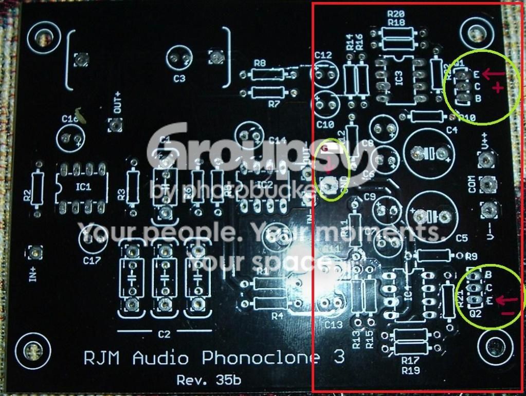
Leave out the components in the red box as they are the x-reg components and not needed if you are using batteries.
Later on if you wish to install the x-reg components and run it from the mains using a separate transformer and bridge rectifiers you can do so, but always get an electrician to wire it up if you are unsure of working with mains voltages.
As for Op Amps, OPA27GP's are good in the input stages and AD797's turn it into a killer unit in the output stages. Thanks to Jim Reeves experimenting.
Get a nice case, LED, switch, RCA connectors and wires and your done.
Now "everybody" can sit back and enjoy the music the way it was intended.:thmbsp:
Here's the good part for DIY'ers you can easily build one of these moving coil only phono stages yourself and embarrass your friends high end phono stages, that's until they build one too
. For very little money you can hear your vinyl the way you never thought possible, enough chit chat for now here's how to do it in three easy steps.
Step 1. Source the PhonoClone 3 PCB's from RJM Audio [No Affiliation!], go here to do that:
http://phonoclone.com/pcb.html
And order these: 1 set Phonoclone 3 : XXX for a set of two boards. (rev. 35b)
Richards one hell of a guy and will look after you.
Step 2. Source the parts, here's a very good BOM for it from Digikey:
8 X 493-3476-ND / CAP FILM 1000PF 100VDC RADIAL - These are Polyester and work well, Wima Pulse Film polypropylene from Mouser are my favs.
2 X PF2105-ND / CAP FILM 1UF 250VDC RADIAL
2 X PF2104-ND CAP FILM 0.1UF 250VDC RADIAL - These should be soldered in parallel to the 1uf's above, they really open up the sound.
8 X P10294-ND / CAP ALUM 100UF 35V 20% RADIAL
8 X BC1084CT-ND / CAP .10UF 50V CERAMIC X7R 10% - These are optional, but I think they work well, solder them across the leads of the 100uf 35v electrolytics above.
4 X P2.20KCACT-ND / RES METAL FILM 2.20K OHM 1/4W 1%
2 X P110KCACT-ND / RES METAL FILM 110K OHM 1/4W 1%
5 X 768KXBK-ND / RES 768K OHM 1/4W 1% METAL FILM
2 X P47.0CACT-ND / RES METAL FILM 47.0 OHM 1/4W 1%
2 X P68.0KCACT-ND / RES METAL FILM 68.0K OHM 1/4W 1%
2 X OPA27GP-ND / IC OPAMP GP 8MHZ SGL LN 8DIP
2 X AD797ANZ-ND / IC OPAMP GP 110MHZ ULDIST 8DIP
4 X ED90105-ND / IC SOCKET 8PIN .300 SOLDER TAIL
Don't forget to work out the values of R1 and R2 and add them to the BOM above, you just need to know what the internal resistance of your cart is e.g. 20 ohms and the output e.g. 0.4mv. Get the values from the spec sheet that came with your cart or online, NEVER measure the resistance with a DMM as permanent damage can be done. And use this gain calculator located here to work them out:
http://www.diyaudio.com/forums/analogue-source/57398-phonoclone-vsps-pcb-help-desk-105.html#post1726608
Thanks again Richard.
Step 3. Connect your batteries together like this:
WARNING: Use a connector that can't be reversed for the batteries as well as a double pole switch that disconnects both the negative and positive leads at the same time or permanent damage can be done to the op amps and/or your MC cart.
Either a XLR connector or something like this:
Then connect them to a switch which MUST be a double pole which disconnects both the negative and positive voltage at the same time, and a LED then the outputs to the points I have marked on the PCB's. You have your +, Gnd, - inputs. Each PCB is one channel so you will have to run the wires to each board.
Leave out the components in the red box as they are the x-reg components and not needed if you are using batteries.
Later on if you wish to install the x-reg components and run it from the mains using a separate transformer and bridge rectifiers you can do so, but always get an electrician to wire it up if you are unsure of working with mains voltages.
As for Op Amps, OPA27GP's are good in the input stages and AD797's turn it into a killer unit in the output stages. Thanks to Jim Reeves experimenting.
Get a nice case, LED, switch, RCA connectors and wires and your done.
Now "everybody" can sit back and enjoy the music the way it was intended.:thmbsp:
Last edited:


