• The move to the new server is done. There are some software and database maintenance updates in process. This has us passing the hat around to help out. We appreciate any donations. Seriously, even a dollar helps. The payment page may be found here - https://www.audiokarma.org/support.html

Coronado Radio Rebuild

Rockyhill

AK Subscriber
Subscriber
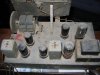
I broke ground, so to speak, on this project. This is a AM/SW radio. After a little dusting (much more required) I disconnected the speaker from the chassis, then removed the chassis from the console.

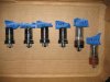
Tubes have been removed. Immediately discovered one has a bad pin (6SK7). I have some of those available so no big deal.

Here's the lineup:
Coronado 6SK7
Truetone 6SK7
Wizard 6SQ7
Wizard 6SA7
RCA 5Y3GT
CBS 6V6GTY

Questions:
Any guess on the age?
What are the chances I can find a schematic?
What needs to be replaced and what can remain? I assume all the caps need to go. Resistors have probably drifted. Not sure what power rating the resistors are. All the wiring insulation is extremely brittle so that will have to be replaced.
Whats a good way to test the transformer?

I've dubbed around with new tube amps a little but never have tried a rebuild before. I don't think this has been plugged in for decades based on the condition of the power cord. (I can safely say it's been several years anyway). Any chance there's still a charge in the caps? Should I ground the chassis and then ground the caps?

I'm going to have many additional questions so please be patient with me!

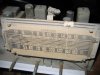
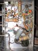
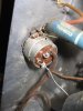
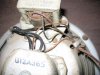
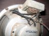
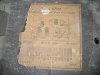
I want to add an aux input. On another thread it was stated that's an easy mod, by connecting to the power switch, I believe. I've included several pictures.
IMG_2142.jpg

IMG_2149.jpg

IMG_2153.jpg

IMG_2154.jpg

IMG_2162.jpg

IMG_2160.jpg

If more are needed for illustration, let me know.

Thanks.

Rob
 
Register to hide this ad
quite an ambitious resto/cleanup project. should be fun.
can you do complete alignment of RF after the refurb is done?
Id say replace all caps with new and same for resistors. the coils will probably be useable or get new ones of same inductance values or make your own. This is where our HAM friends can help if needed. SW ya know. try google the make/model for more info or schem.
 
I found a schematic.View attachment Coronado Schematic.pdf

I don't have the equipment to align the tuner. But I really intend to use this as an amp with an aux input connected to an iPod. AM and SW aren't my thing, honestly.

Looks like it was built by Wells-Gardner 1942, according to the schematic.
 
Last edited:
I was gonna say, Late Thirties/Early Forties. After awhile, you get to where you can "Mouth" 'em pretty well...
 
Let me amend my goal. I want to restore this to original functionality, plus add an AUX input. While I would rarely use the AM/SW function, it would certainly be fun to have those bands. My kids would get a kick out of hearing some distant signal via SW. The primary use will still be to connect an external signal for streaming audio or mp3. It will be placed in our dining room, which currently lacks a music source and placing a conventional system there is not an option (read: low WAF). I plan to restore the cabinet and replace the grill cloth.

Now for my fellow AKers:

I will proceed with the restoration if the existing transformers can be salvaged. How can they be tested? I want to avoid having to source replacement of hard to locate components.

Schematic is up a few posts.

Thanks
 
Do you have the speaker and its output transformer? The output transformer probably is mounted on the speaker. The speaker plug probably has connections from the B+ line filter capacitors, to the plate of the 6V6, the neg terminal of C19a and chassis ground. On the speaker end, the B+ and plate lines would go to the output transformer primary, while the ground and neg to C19a would go to the field coil on the speaker. The speaker is an electrodynamic type. If you do not have the output transformer and speaker, I would still think you could find a suitable output transformer for the 6V6 and use it with a modern permanent magnet speaker. There are pointers on this on the web - search for "electrodynamic speaker replacement." The rest of it looks quite restorable, assuming the power transformer is okay.

Look up "dim bulb testing" for info on safely checking the power transformer. Also, good resources are the vintage radio forum on Video Karma and the Antique Radio Forums (Google it).

Edit - just noticed the schematic shows the DC resistance of the transformer and coil windings - a good start for power off testing of those components. Also, note that the voltages listed on the second page are measured with a 1000 ohms per volt meter. They will measure higher with a modern DMM unless you have a shunt resistor across the meter leads. The shunt resistor should be 1000x the maximum voltage on the meter scale being used - somewhere in the 250k-500k range.

Just listing some of the gotchas that got me on my first restoration.
 
Last edited:
Do you have the speaker and its output transformer? The output transformer probably is mounted on the speaker. The speaker plug probably has connections from the B+ line filter capacitors, to the plate of the 6V6, the neg terminal of C19a and chassis ground. On the speaker end, the B+ and plate lines would go to the output transformer primary, while the ground and neg to C19a would go to the field coil on the speaker. The speaker is an electrodynamic type. If you do not have the output transformer and speaker, I would still think you could find a suitable output transformer for the 6V6 and use it with a modern permanent magnet speaker. There are pointers on this on the web - search for "electrodynamic speaker replacement." The rest of it looks quite restorable, assuming the power transformer is okay.

Look up "dim bulb testing" for info on safely checking the power transformer. Also, good resources are the vintage radio forum on Video Karma and the Antique Radio Forums (Google it).

Edit - just noticed the schematic shows the DC resistance of the transformer and coil windings - a good start for power off testing of those components. Also, note that the voltages listed on the second page are measured with a 1000 ohms per volt meter. They will measure higher with a modern DMM unless you have a shunt resistor across the meter leads. The shunt resistor should be 1000x the maximum voltage on the meter scale being used - somewhere in the 250k-500k range.

Just listing some of the gotchas that got me on my first restoration.

Thanks altbrewer (based on your username, it looks like you have another hobby!).

I do have the speaker and yes, the output transformer is attached to it. I will look at the transformer this weekend.

Are there ways to test the IF transformers without power? I've been looking at various antique radio sites and the IF transformers seem to get corroded from use, lack of use and time.

Initially I thought this would be a relatively easy restoration, but now it's getting more complicated. I think my go/no go decision will be based on the condition of the transformers. There's a lot of brittle insulation in the old gal. Discrete wires I can replace. Transformers are another thing.

Rob
 
I have several other hobbies, one of which is reflected in my username:thmbsp:

The good thing about your IF transformers is that they are tuned by padder capacitors and have no ferrite cores to freeze up inside the coils. I'll bet they are good if each coil has approximately the resistance noted on the schematic.
 
I found a schematic.View attachment 310637

I don't have the equipment to align the tuner. But I really intend to use this as an amp with an aux input connected to an iPod. AM and SW aren't my thing, honestly.

Looks like it was built by Wells-Gardner 1942, according to the schematic.

earhole alignment should do the trick just fine. Tweak the IF cans in sequence while tuned to a weak station, adjust for best volume. Adjust the oscillator at the top and bottom to known stations close to whatever frequency it says to use. It may not be quite by the book, but it'll be plenty good enough for most purposes.
 
I've resumed this project. The power transformer tested fine when I measured the resistance compared to schematic. As far as the speaker field coil goes I'm a little unclear how/where to measure the resistance.

The speaker itself is in very good shape, from a visual perspective. I used Howard Restore-a finish on the console - wow, does it look great! Cleaned up water marks, scratches, etc. Need to replace the grill cloth.

If anyone can suggest how to measure the field coil that would be appreciated. Next step is to catalog the caps and make a list for replacement.
 
Back
Top Bottom