• The move to the new server is done. There are some software and database maintenance updates in process. This has us passing the hat around to help out. We appreciate any donations. Seriously, even a dollar helps. The payment page may be found here - https://www.audiokarma.org/support.html

Citation II hack

Hi Guys & gals,
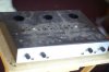
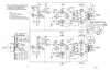
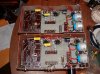
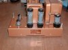
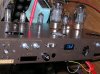
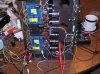
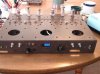
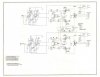
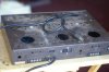
I am modifying my Citation II as it's in poor shape cosmetically,and the chassis has been modified by people before me,I have 2 chassis,one came from the auction site,the other is a complete amp in poor condition,my goal is to try a few things and if it doesn't work out ,I will just rebuild it,I am not crazy about the stock amp,because it runs too hot,and sounds a little too tight for me.I have a BTH A1A that sounds terrific and if I can get the Citation to sound like it, I would be extremely happy I have a schematic of the amp as far as I built it,I copied the driver circuit from the BTH,and the output from the carver modified schematic,but I am not an engineer,so I am soliciting advice,I have run one channel with my bench power supply,and a Bogen output transformer my bench supply doesn't have enough bias current to run the amp to full voltage.I am a little reluctant to remove the transformers from the intact amp until I have some of the bugs figured out on the bare chassis.attached are pics and schematic of my project so far,also the BTH
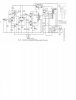
Bth A1A schematic.jpg
E-bay Citation 2 chassis 2.jpg
E-bay Citation 2 chassis 1.jpg
Caqrver mod cit 2.jpg
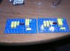
Citation2 boards top .jpg
Bth A1A amp bottom.jpg
Bth A1A side.jpg
Citation 2 meter test.jpg
Citation 2 test with bogen transformer .jpg
Citation 2 bias meter.jpg
 
Last edited:
Register to hide this ad
The meter will fit the stock citation II, it is glued to the back of a smoked lens with crazy glue it is mounted flush to the back side of the chassis.I changed the cathode resistors to 10 ohm so the meter would read MA directly and blacked out the decimal point

(on the auction site) DC 0-33V Blue 0.36 LED 4 Digit Digital Voltmeter
I am unsure if the ac balance is done correctly,and the feedback loop is not currently hooked up,I need advice on how to figure out the feedback loop, as neither circuit is completely as designed.I have an ocilliscope and signal generator to start with,I also have a heathkit Harmonic distortion analyzer,and IM distortion analyzer that need to be straightened out for later.
 
Last edited:
The meter will not read negative voltage,so the AC balance function will not work.I am keeping an eye out for a similar 3 digit meter with 4 wire input with a + amd - in front
In a related question,can AC balance be read by comparing the current with and without test signal on a pair of tubes?
Power for the meter was acheived by voltage doubling the 3.3 volts available on one filiment wire.
 
Last edited:
Excellent idea, the digital readout. I always thought the stock bias adjustments on the Citation II the best and easiest ever on a vintage amp and you've improved on that. Nice!
 
If I could have gotten a +/- 9.99v meter it would have beem perfect.
I didn't have a meter with the chassis when I bought it,So this was the best alternative
 
I don't have an issue with modding the CIT II circuit an going how your proposing.

BUT I wouldn't use ECC83 there as the splitter/driver, it just won't have the "drive"
to push the outputs proper, you'll have loss of power and frequency response with
it in that position, I'd suggest if you want to keep gain similar move it to an 12AT7.
 
I don't have an issue with modding the CIT II circuit an going how your proposing.

BUT I wouldn't use ECC83 there as the splitter/driver, it just won't have the "drive"
to push the outputs proper, you'll have loss of power and frequency response with
it in that position, I'd suggest if you want to keep gain similar move it to an 12AT7.

Would I keep the resistances the same around the tube?
The BTH was driving EL34's with the ECC83,Bob Carver's 305 use a ECC 81 drive 6 KT88's
I will be using KT88's to start with,The extra tube sockets will likely have VU meter tubes in them (EM800's)
Off to work,back in the AM
 
Last edited:
I haven't analyzed the rest of the circuit, and can't read it that well.
(more then likely plate loads lower for the 12AT7 in there though)

But yah ECC81 being the same tube as the 12AT7 is an better choice.
(It'll still have a lot of gain, a 12AU7/6CG7 would be a nice choice to)
 
Last edited:
You might consider a CCS in the shared cathode, or tail, of the phase splitter and make the anode load resistors equal. It will improve the phase splitting.

John
 
You might consider a CCS in the shared cathode, or tail, of the phase splitter and make the anode load resistors equal. It will improve the phase splitting.

John

Hi John,
I found the first schematic for a CCS,but it is a little bulky,it took me a while,because I didn't know the acronym,would the second schematic work for a 12AT7,I'm not sure of how much current the tube will pass.
 

Attachments

  • ccs3a.JPG
    ccs3a.JPG
    17.9 KB · Views: 54
  • ccs3.jpg
    ccs3.jpg
    46.7 KB · Views: 55
For a 12AT7 in an LTP you'd be looking at setting the current to something like 6-8ma total for the pair.
(and no your posted amp schem I can't read to give you any suggestions)
 
Last edited:
I've used a couple of versions of CCS's. The one I've used most often is a cascode pair of depletion mode mosfets. You can read a great article about CCS's here from Gary Pimm:

http://www.pimmlabs.com/web/Active_loads_and_signal_current_control.html

I've used CCS's for a number of applications and in a number of amps: have fed glow tube shunt regulators, used the follower output for low output impedance in the line stage, used them in the cathodes of LTP's and in the cathodes of PP output stages to make class A differential amps. They work very well in all these applications and I don't think the tube sound is lost, they just get more clear and effortless without being hard or harsh as I perceive SS.

Good luck and have fun,
John
 
For a 12AT7 in an LTP you'd be looking at setting the current to something like 6-8ma total for the pair.
(and no your posted amp schem I can't read to give you any suggestions)

I am having trouble figuring out how to get a high res schematic posted,even on imageshack it gets downsized
 
Last edited by a moderator:
I am having trouble figuring out how to get a high res schematic posted,even on imageshack it gets downsized

If you've got a "full size nicely readable" schematic on your computer just crop out
or cut and paste the relevant portion with something like MsPaint, save and post it.
(that's how I do it with no hosting site, so that it stay's on AK)
 
Bruce Moore already worked out a 5687 front end for the Citation II OTs. I have his schematic around here I believe. :yes:
 
If you've got a "full size nicely readable" schematic on your computer just crop out
or cut and paste the relevant portion with something like MsPaint, save and post it.
(that's how I do it with no hosting site, so that it stay's on AK)

I was going to try hosting,but my provider dosen't offer it
I cropped out the part I have questions about I hope this works.
I do have 25 of the 5687's
 

Attachments

  • c2driver.jpg
    c2driver.jpg
    49.2 KB · Views: 169
Last edited:
If I were to use the zeners,I would need 5 watt,Correct? 33v at 10ma (~3watt) Is there any noise in a zener? Would I put a cap across them?
 
Here's the MFA-120 by Bruce Moore.

attachment.php
 

Attachments

  • mfa120p1.gif
    mfa120p1.gif
    43 KB · Views: 219
Last edited:
Back
Top Bottom