Improving the Fisher SA-100 with EFB II

dcgillespie

Fisher SA-100 Clone
Subscriber
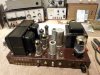
For EL84 fans, the Fisher SA-100 has always been the stuff drool was made of. Big beefy transformers, neat, compact size, and certainly not last or least, the name and look of -- The Fisher. Within the EL84 basic stereo amplifier group, the SA-100 easily takes top dog ranking, besting similar amplifiers from Eico, Dynaco, Pilot, and others -- if only by the size of its transformers alone.

The closest competitor would be the Dynaco offerings due to the quality of their transformers. But these amplifiers were limited by other factors within their design. However, with the addition of my EFB(tm) modification to those products, the modified Dynacos can then handily best the power and distortion levels of a stock SA-100 across the entire audio spectrum, in spite of their overall smaller transformer set. Additionally, the modified Dynacos also run their output tubes at lower quiescent currents than either their original designs -- or that which the SA-100 calls for, which certainly equates to cooler operation, and longer tube and component life. However, the original EFB modification as presented was only applicable to UL designs and certain select pentode designs. It was not appropriate for the Fisher SA-100.

With numerous requests piling up concerning the installation of EFB in a pentode based output stage, I thought it best to detail its implementation into what is arguably the best pentode EL84 design ever produced. Additionally, because it is a fixed bias amplifier to begin with, it offers the ability to showcase the idea of using an EFB supply regulator to provide the "Enhanced" element of EFB, since the fixed bias element has already been provided for us by Fisher. This is a topic I touch on only very lightly in my original article on EFB.

In the SA-100, the EFB supply regulator element then becomes only a portion of the overall EFB II modification, with the remaining portion being the additional EFB elements that control the screens of the pentode output stage.

To develop and prove the theory regarding the EFB II concept, a clone of the SA-100 was constructed, upon which performance was then measured and documented. You can find the details of that project over on the Tube Audio forum here:

http://www.audiokarma.org/forums/showthread.php?t=466229

I am still attempting to post the final schematics of my clone on that thread to finish it out, but have been hindered by the size of the files that each page of the schematic represents. My latest effort to post them has a fellow AKer attempting to shrink them appropriately so that the forum website can accept them for direct posting. If you are following this thread, you might check in on that thread from time to time to see when that effort becomes successful.

In any event, that thread developed enough interest that another fellow AKer sent me his stock, but dormant SA-100, to use in developing a data base of a real SA-100's stock performance for comparative purposes. The adventure of this thread will start with my work from day one on that unit. This initial post serves only to introduce what is to follow, wherein that unit is repaired and brought to stock Fisher specs, performance measurements made and recorded, and then the surgery begins. Along the way, I will document the operation of EFB II, so that others can install it in numerous other settings appropriate for its use if they wish. In the end, this will result in a new article for the Tronola website, documenting all the possible versions of EFB and EFB II (there are four of them), so that any and all interested DIYers can pick and chose the EFB circuits that are best for their projects.

I can tell you this. To date, I've already done the basic repairs to the SA-100, and have it running properly according to its original design. And, I've already developed the data base of its stock performance as well, which marks where I currently am with this adventure. By comparison, if the the results of my EFB II clone are any indication, this is going to be fun!

So much more to follow -- with pics of course.

Dave
 
Dave, you set the standard with that clone SA-100 :thmbsp: What a great reference for the rest of us who hope to come by a SA-100 someday - me in particular.
 
Hey, Dave - do you think a set of original Z-565 OPTs would work in that SA-100 clone? If so, I might have a new project. :D

-D
 
I'm wondering how it would work on a 6BQ5/7189 Fisher Tube amp/receiver or even the bigger 7591/7868 output units. Something to mull over.
 
Bruce -- Thanks so much for the kind words. I have ended up enjoying listening to the clone immensely!

Derek -- If you use the Dynaco transformers in UL mode, you are effectively just building an ST-35 -- by topology anyway.

The Dynaco's would be appropriate impedance wise for the SA-100 circuit in pentode mode, but would likely not let it perform as well as the original SA-100's transformers did since they are smaller transformers. The UL connection helps to allow the Dyanco transformers to "hang on" to the output tubes better than a straight pentode only connection does as the transformer nears saturation. As a result, with all else equal, a UL transformer can be slightly smaller for a given performance level than a transformer designed for similar pentode performance is. Therefore, in pentode mode, the Z-565 transformers will work, but be at a disadvantage as compared to the original transformers that Fisher used.

Larry -- if you check my final main posting on the clone article, you will see that ultimately, EFB II will work very well in deed for 7591/7868 based amplifiers. After I get done with the SA-100 installation, I will start writing my article for Tronola, and in it, include all the versions of EFB(tm) and EFB II, so that folks can pick and chose the best version for the project at hand.

Should have and update and some picks posted on the progress of the SA-100 tomorrow.

Dave
 
Bruce -- Thanks so much for the kind words. I have ended up enjoying listening to the clone immensely!

Derek -- If you use the Dynaco transformers in UL mode, you are effectively just building an ST-35 -- by topology anyway.

The Dynaco's would be appropriate impedance wise for the SA-100 circuit in pentode mode, but would likely not let it perform as well as the original SA-100's transformers did since they are smaller transformers. The UL connection helps to allow the Dyanco transformers to "hang on" to the output tubes better than a straight pentode only connection does as the transformer nears saturation. As a result, with all else equal, a UL transformer can be slightly smaller for a given performance level than a transformer designed for similar pentode performance is. Therefore, in pentode mode, the Z-565 transformers will work, but be at a disadvantage as compared to the original transformers that Fisher used.

Dave,

Given that original Fisher SA-100 transformers cost what we call "real money", are there any suitable substitutes that are a bit more beer-budget? Or is it pretty much requisite that you use big-ass iron with a lowish (e.g. 6.6k or so) impedence? For example, would the iron from an X-101 work well (given that it is pentode-only)? I'm guessing that Edcor and Hammond iron wouldn't be a good choice given that they are UL OPTs.

Thanks!

-D
 
Hi Derek -- The iron from an X-101 is very good in its own right, but is still somewhat smaller than that used in the SA-100, which would again, limit LF performance. But, this brings up an even more basic issue needing attention here.

I have conducted numerous tests on both of the SA-100's OP transformers from the unit I have here, and can say without a doubt that Sams has done it again. In particular, the transformers on the SA-100 are in fact 7800 ohm units (7831.47 ohms to be exact) AS MEASURED USING THE FULL SECONDARY winding. This is the ONLY way to measure the primary impedance of a given OPT, as it is the full secondary winding that forms the basis of a transformer's design to begin with. The 4 & 8 ohm taps then are simply just that -- taps on the full 16 ohm winding configuration. The 16 ohm winding is NOT a derivative of the 4 or 8 ohm windings. Therefore, it is always the full secondary winding that is used to determine primary impedance.

Because of the multiple windings and highly interleaved winding process used in high quality OPTs, the 8 ohm tap cannot always be placed at exactly 8 ohms, but is a close approximation. This usually results in the 8 ohm tap reflecting a slightly lower impedance, and the Fisher transformers used in the SA-100 are no exception. In this case, the 8 Ohm tap reflects 6961.3 ohms from an 8 ohm load, which may be the tap that Sams used to generate their data from -- which in any event is wrong for the reasons I have indicated. Either way, their data is "a bit off" regarding these transformers.

Using the 4 ohm tap for measurement usually produces far less error, as the 4 ohm tap simply uses 50 % of the windings used to make up the full 16 ohm configuration. Therefore, any error present then is usually quite small. In this case, the Fisher SA-100 transformers reflect 7901.23 ohms back to the output tube plates with a 4 ohm load placed on the 4 ohm tap. This is within 1% of the impedance reflected from the full 16 ohm winding with a 16 ohm load applied, while the 8 ohm tap only reflects 88.9% of the full secondary impedance.

In any event, since the primary impedance of the X-101 transformers is very close to this impedance, they would in fact work from an impedance standpoint, although with the LF limitations previously noted. And (as I know you know!), the NFB network would require some alterations as well.

If you are interested in building your own clone of the SA-100, I would recommend that you use the transformers I did, and have recommended to others to use -- who have now used them with success as well. My transformers came from a Heath AA-100 amplifier, and have proved to be every bit the equal of the original Fisher transformers -- in nearly every way. First, their impedance is so close as to be insignificantly different. Second, their lam stack is IDENTICAL in size to that of the SA-100 transformers (although they mount up differently). Third, they come from a pentode based 7591 amplifier rated for 25 watts RMS per channel, and finally, the measured performance of my clone shows them in fact to perform at least at the level that the SA-100's transformers will.

As an added bonus, if you follow the basics of my clone version, you also have all the NFB issues for these transformers worked out for you, eliminating that element of concern.

Once EFB II is installed in the SA-100 and its performance is improved, then we'll know for sure. But every indication is that whatever the SA-100's transformers could do, the Heath (Stancor) transformers can do just as well.

I hope that helps!

Dave

Got an extra pair of AA-100 transformers you want to sell me for $40? :D

-D
 
Eico ST-40 outputs might be a candidate..
(even the power tranny should work to)

Maybe even converting an ST-40 over, using either 7591 or 6V6 to use the octal output sockets. ;)
 
Last edited:
Dave,

Again .. I am in awe of what you did here.

And even better is the discussion and percolation of ideas this has instilled.

Good Job!!

Frannie
 
Last edited:
I'm not new to tube amp design and construction. I've built a handful of guitar amps. However, I am new to Hi-Fi amps, especially the aspects of feedback, bandwidth, and distortion reduction. I was thinking of buying some books on Hi Fi tube amp design and construction to further my knowledge, but why bother. All I have to do is search this forum for Dave Gillespie's comments!

Thanks Dave, I am learning a lot from your posts. I really appreciate the fact that you take the time to post as much info as you do, and that you are sharing your ideas openly.

Sincerely,
Chappy
 
We Begin

The SA-100 was a very good design for its day. The output stage is an exercise cut right out of the RCA Receiving Tube Data for the 7189, it employs a heavy-duty power supply, and a high current screen bleeder-regulator circuit to help regulate the screen voltage. Such measures are not found in any other EL84 family pentode amplifier challenger to my knowledge.

Still, it is not without its opportunities. The screen bleeder-regulator circuit is hardly as effective as can be achieved today, and it, along with the B+ dropping resistor at the rectifier tube adds over 20 watts of heat dissipation underneath the hood of this puppy. I am glad I'm working on this sucker in cooler weather, because it is one hot potato in normal operation -- even at this late date.

Also, with it being a fixed bias design, as the B+ voltages fall to the plate and screen circuits when power output is increased, it upsets the operating position established under quiescent conditions, since the bias voltage remains basically unchanged under any and all conditions of power output. This causes distortion to elevate as power is increased, and if both channels are driven (duh, this is stereo), it increases even more.

Finally, as the B+ falls, it falls by a greater percent in the screen circuit, since any voltage drop there is the product of not only any drop in the main B+ supply, but also due to the inefficiencies of the screen bleeder-regulator. Ultimately, that means then that as power is increased, the grid bias remains stable, while the screen voltage falls off at one rate, and the plate voltage drops off at another. In other words, the conditions of the original operating point have been completely destroyed.

Traditionally, there has only been one way to produce the ultimate in performance from a pentode output stage. Regulate it. Not just the grid bias, or the screens, or even both, but all of it. The plates, the screens, and the grids. That way, as power is increased, distortion remains low because the operating point has been locked into place. Since the voltages never waver in spite of power produced, distortion is always low. But the chassis of the SA-100 is one cramped little guy. It would be quite a feat to install such regulation in this amplifier. So what can you do? Enter, EFB II.

In a nut shell, EFB II is not comprised of regulators in the traditional sense, but does employ regulators to lock the quiescent relationship of the elements together, while the main B+ supply still remains unregulated. This is the heart of what "Enhanced" Fixed Bias is all about, and provides a number of benefits.

1. It makes for a very small and simple circuit, as compared to that which a full complement of regulators would generate.

2. It maintains the low distortion point regardless of power output, and regardless of deviations in the main B+ supply.

3. It creates greater power output due to less voltage drop in the screen grid supply circuits.

4. It generally allows for a lower quiescent current operating point (at which lowest distortion is achieved), than could otherwise be used with traditional methods to power the individual tube elements.

5. It will allow this particular amplifier to operate much cooler than the original design will, eliminating nearly 30 watts of total heat dissipation between the reduced quiescent current draw through the tubes, the screen-bleeder circuit, and the main B+ dropping resistor.

Therefore, the main B+ voltage can and will still sag with increasing power output, but with EFB II, ALL of the tube elements sag together while retaining the same initial relationship set under quiescent conditions at all times. Therefore, reduced B+ will ultimately reduce power of course, but with EFB II, it will not increase distortion.

The concept of the original EFB(tm) circuit and EFB II is the same, but EFB II adds the necessary circuits to maintain the initial relationship set for the screen as well, throughout the entire power range of the amplifier. Because this allows for less overall voltage drop in the screen circuit, maximum achievable power output is increased along with the lower distortion produce by maintaining the low distortion operating point.

With that then, here is the basic plan:

1. Repair the amplifier as required to facilitate accurate measurements of stock amplifier performance.

2. Remove the damping control circuits. This is an antiquated feature, and its removal will allow two terminals on each output strip to be used as individual output tube current measurement points, as the original design only allowed for measurement of the total current draw of each channel.

3. Install individual 10 ohm cathode resistors to allow for current measurements of each output tube at the new terminals created above.

4. Install individual 100 ohm screen stability resistors. This will allow for the use of a screen supply source of much lower impedance without any concerns of output tube arcing.

5. Remove the old screen bleeder-regulator circuits.

6. Install the screen voltage control portion of EFB II

7. Install the bias supply regulator portion of EFB II.

8. Check out, retest, and document performance results.

Pics include:

1. The candidate. It even arrived with all original Fisher tubes (except the rectifier), but had not been operated in years. It also arrived DOA. A quick check of the tubes revealed that the rectifier tube and small signal tubes were still good, while the four output tubes were well matched from a quiescent current standpoint, but produced 107.7%, 97.8% (both good), 75.1% (weak), and 53.1% (very bad) of average new power output (ANPO). Incidently, both the weak and bad tubes read nearly GOOD on my B&K 747, and the weak tube in fact read GOOD on my Hickok 533A. I mention this only to reinforce the point that Gm testing of power tubes delivers very unreliable results. Thankfully for this project, the owner supply some NOS Russian 6P14P-EBs for replacement.

2. Searching for what died. Man there are a lot of power resistors in this thing -- exceeded only by the number of vent holes drilled in the chassis! I can only imagine how hot this amp got operating in the back of a closed up console! (which I understand is where it came from) The ultimate problem was traced to the plate load resistors of the first stage in each channel being open -- I don't mean a little open. We're talking no measurable resistance at all!

3. Initially the can cap formed up and measured just fine for performance measurements. However, about 3 hours into the second day of general listening.........

4. One the first day, generating a slew of stock performance measurements.

5. Enough measuring already. Stuff is starting to get ripped out now. The damping control circuits have been removed, as have been the original cathode measurement resistors. Cathode wiring is in the process of getting re-routed, and on it goes. A restuffed can cap stands ready for install to replace the old pressure cooker.

Next post, performance results of the original design to establish a point of comparison, and more pics of more progress.

Dave
 

Attachments

  • SAM_0016.jpg
    SAM_0016.jpg
    89.3 KB · Views: 467
  • SAM_0014.jpg
    SAM_0014.jpg
    98.3 KB · Views: 423
  • SAM_0020.jpg
    SAM_0020.jpg
    83.3 KB · Views: 406
  • SAM_0018.jpg
    SAM_0018.jpg
    96 KB · Views: 402
  • SAM_0025.jpg
    SAM_0025.jpg
    109.5 KB · Views: 440
Whoops!

Well, I gotta admit -- I really didn't think I would be dealing with this issue on this unit.

The chassis on some of the earlier Fisher equipment has a high copper content (and therefore, look), which would certainly lend to the thought of excellent conductivity. Therefore, the concerns of time and using multiple mechanical ground points through out the build should be greatly reduced, right? Well, dissimilar metals are dissimilar metals, regardless of what the composition of those dissimilar metals are. This fact, time, and an ohmmeter -- once again -- prove it. A number of ground points show somewhere between 5 and 10 ohms, with one (minor ground point) showing as much as 15K!

This means that to do this job correctly, I need to take a pause, and fix the ground issue correctly. At this point, the damping control circuits have been removed as has been the original cathode circuit wiring, and individual 10 ohm cathode resistors have been installed using the new TPs created. The original screen wiring has also been removed, and individual 100 ohm screen stability resistors have been installed. I was in the middle of replacing the can cap when the grounding issue was discovered.

To be completely fair in the comparison then, once the ground issue is repaired, a complete retest is in order as I consider all the old performance data contaminated by the poor grounds. It will be a lot of work, but there is no other way to make things right. The retest will still include the new 10 ohm individual cathode resistors, and the new 100 ohm screen stability resistors, but these elements have long been shown to have no detrimental impact on performance -- and in reality, can only help by allowing for a more accurate DC balance capability, and ensuring no possibility towards unstable screen operation . Also, the new can cap simply removes it as any possible negative element, and the damping control circuits were not used in the original performance testing anyway. Therefore, the retest will still effectively represent the unit's stock performance capabilities.

The impact of the ground resistance may prove to be insignificant in terms of measured performance. But the performance data from the measurements I previously took was published as representing the stock design (and was the basis of my own listening observations as well), which clearly, the current state of the grounding system does not represent -- at least in terms of electrical performance.

So, I will take a time out to resolve the issues at hand, retest, document, and post those results here, and then pick up where I left off.

Better I found it now rather than later!

Dave
 
Unfortunately, this generation of Fisher gear is old. It strikes me as a full generation older design-wise and in implementation than the stuff coming out starting in about 1962.

I suspect that there are similar lurking problems in my Fisher SA-300.

I'll be watching this thread with interest and stocking up on simple things like star shaped grounding washers. I might adapt some of your findings (aka, glom on vicariously) to that SA-300's EL-34 outputs. I think that amp also has a lot of potential.

My experience with reliability on the brass faced early receivers, integrateds, and power amps is that they're not up to the standard of the later stuff in terms of long-term reliability, though that may simply be because of manufacturing capabilities at the time. Sometimes it's just simple things like that the early power cords dry out and expose the copper.

While they're more cost-no-object than the later stuff, they seemed to learn and improved for the post '61 gear based on their experience over there in Long Island City and Allendale, PA.

I'm always surprised why this stuff doesn't have chokes as part of their power supplies though.
 
Last edited:
Don -- I agree with your comments 100%+. The earlier stuff was designed with more of a cost no object approach, but lacked the basic quality of wiring and small components like resistors and such. Therefore, I too believe that while the 62 and later gear was more general (but still higher end) consumer related than the earlier gear was, it was also built better as well.

To punctuate this point even more, quite frankly, the wiring of this SA-100 is rather rough, with blobs of solder, excess lead lengths bunched up, and the like. It's still a solid build, but definitely lacks the neatness of the later gear. I had the exact same experience with a couple of 80AZs that I did extensive work on as well.

Something tells me that this project is going to end up as more of a rebuild with a modification installed along the way, rather than simply adding the modification and calling it a day!

Dave
 
Dave,
Is the SA-100 a true dual mono amplifier after the power supply like the SA-300?
The SA-300 has two tube rectifiers, one for each channel and it appears that everything after the power supply is dual mono.
Each has a 12AX7 voltage amplifier and a 12AU7 for phase inversion.
In the SA-100 photo, I only see one 5AR4 rectifier in your phono and are the 7247s doing both amplification and phase inversion?
 
Last edited:
Don -- Unless you have a modified SA-300, the design of the original SA-300 has the dual rectifier tubes wired in parallel, with both tubes then serving both channels in the conventional manner. It was never wired with one rectifier tube serving one channel to my knowledge.

In the SA-100, a single 5AR4 rectifier is used serving both channels as well, and each 7247 provides the the AF amplification and phase inverter needs for each channel.

Hope this helps!

Dave
 
Back
Top Bottom