• The move to the new server is done. There are some software and database maintenance updates in process. This has us passing the hat around to help out. We appreciate any donations. Seriously, even a dollar helps. The payment page may be found here - https://www.audiokarma.org/support.html

AU-517 Recap/Restore with a little sting in the tail

skippy124

Super Member
Hi,
A friend recently acquired an AU517 and asked me to check the unit over and do a recap/clean etc, and I thought I’d share the work that was done. And as the title suggests, there was a little hiccup in the work that will be revealed towards the end.
The work to be done was as follows –
Full clean, replace all electrolytic caps (Panasonic FC and Nichicon HE) except the main filter caps, replace all fuse resistors, replace the VD1212 diodes (2X1N4148) and the Bias pots with 10 turn versions.
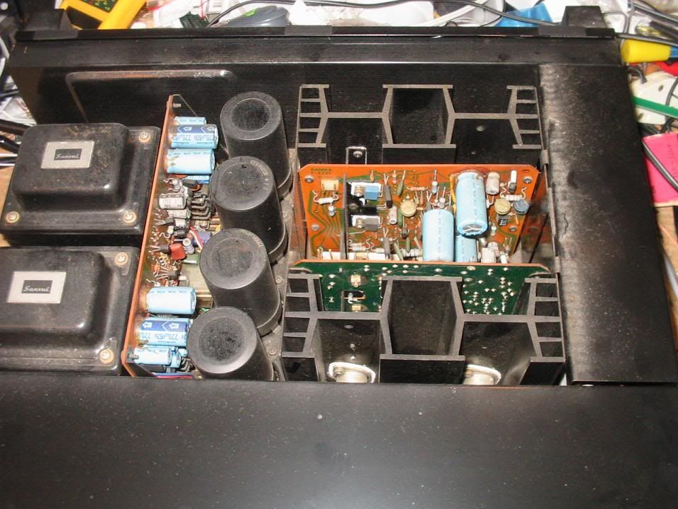
The unit as received
AU517frontbc.jpg

AU517frontbc2.jpg

AU517topbc.jpg

AU517topbc1.jpg

AU517topbc2.jpg

A quick operational check was done (the owner advised that the unit was working) and all appeared fine, it came out of protection, bias and offset checked OK, and a quick listen showed it worked OK (or at least appeared to…. more about that later)

First off were the driver boards
 
Register to hide this ad
Driver boards were removed from the amp and separated from their heatsinks and caps removed

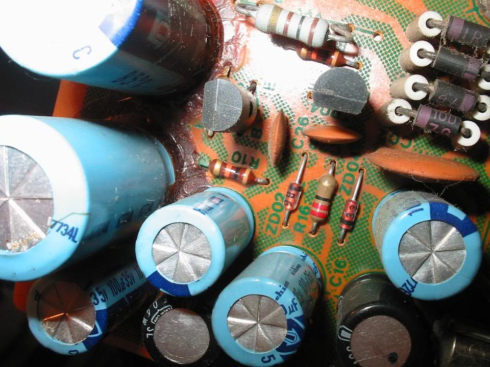
The dreaded glue

AU-517driverglue.jpg


All caps removed and glue cleaned

AU-517driverglueclean.jpg


New 10 Turn Bias pots with leads modified to fit pcb hole spacing

AU-517driverbiaspotmod.jpg


New caps and bias pots fitted and boards reassembled to the heatsinks (Panasonics Stacked films were used for the 1uf 50v electros)

AU-517driverfinished.jpg


These were then put aside until final re-assembly.
 
Next in line was the Power Supply board
Partially removed from the chassis

AU-517PSUbefore.jpg


More of the glue

AU-517PSUGluebefore.jpg


AU-517PSUGluebefore1.jpg


With some of the caps removed

AU-517PSUGluebefore2.jpg


Glue removed, caps replaced, ready to refit to the chassis

AU-517PSUafter.jpg


And back in place

AU-517PSUafter1.jpg


One of the things that was discovered when the Power supply board was done was a previous repair, and the substituting of some component values in the protector circuit.


AU-517protectorcctchanges.jpg


C601 changed from 47uf to 100uf, R601 changed from 390 ohm to 180 ohm, R608 change to 22K and TR603 changed to a 2SC2320. Looked like there had been some previous problem with the protector circuit, and I decided to change back to the original components as per the schematic ( I also checked against a 517 I have, and it agreed with the values shown in the schematic).
Next was the Tone Control and Equaliser boards
 
Here is the Equaliser board recapped, and the 82 ohm fuse resistors and VD1212 diode pairs replaced

AU-517equaliserafter.jpg


I didn’t take any pics of the Tone Control board, it is a pretty simple board to recap in the 517

The front panel and knobs were given a good clean, and I also cleaned/polished the heads of all the screws that were removed.

AU-517screwpolish.jpg


AU-517driverinstalled.jpg


AU517frontac.jpg


AU517frontac1.jpg


Once it was all back together, it was time to put it on the dim bulb tester and see how she behaved with power applied…… now to the sting in the tail……
 
Hooked her up, power on….. bright then dim…. All looking good…… and the protector light just kept on flashing, and flashing, and flashing….. hmmmmm.
Checked offset…. Both channels were ok. Checked base drive to relay transistor – OK, checked rail voltage of protection circuit, was fluctuating around with the flashing for the protector LED – smacked of not enough rail voltage, and my thoughts went back to the mods that had been done the protector circuit, lower series feed resistor for the + rail, larger filter cap, reduced time constant resistor…. Looks like this had been a problem that the previous person that worked on the unit had circumvented with the component changes that I mentioned in an earlier post.

OK, lets do some cold checks on the left channel power supply (the protector circuit gets its power from the left channel transformer). A resistance check of the main fuses showed that F03 was open, even though it appeared to look fine - always check fuses with a meter, don’t rely on a visual check


AU-5176AfuseF03.jpg


This unit is a universal voltage model, and has fuses in both halves of the secondary outputs for each channel. A new fuse was installed, and the unit turned on…… dim bulb on full brilliance… there is a short somewhere…… Main rectifiers checked out OK, so I disconnected the output of the left channel supply to the filter caps at the power supply board… short still there…. So I removed the power supply board for further investigation. First thing to look at was the two rectifier diodes for the protector supply (D601 and D602), and guess what, D602 was short circuit


AU-517protectordiode.jpg


AU-517protectordiode1.jpg


A new diode was installed, the power supply board reinstalled and reconnected, and the unit was powered up again….. Bingo, dim bulb indication was normal, and the unit came out of protection as expected.
It appears that D602 failed short sometime in the past, taking out the main fuse F03, but not visually

Whoever repaired it did not notice (or check) that the fuse had gone, and this would have led to the low rail voltage for the protector circuit. He substituted the components in the protection circuit in order to get the relay operational again, and even with this main fuse blown, the amp will still operate OK on lower volume settings, as it would be getting half wave rectification via the one half of the transformer secondary winding that was still in circuit. Once he got the relay to click in and it sounded “OK”, it must have appeared to him that the fault had been fixed……….
Well it is now!!

Cheers

John
 
Nice work, on both the restore and the repair.

Sometimes tracking down the bad parts can be very time consuming, but is worth it in the end.

Rob
 
Well done John !

Caution, knowledge, experience, and a DBT - a perfect combination :thmbsp:

And to cap it all off (pun intended) a nice restore.
 
Last edited:
Nice work.
I have a 517 on the bench that I would like to get at this winter. Pics like these help a lot.
 
Thanks for the comments gents!!

Always makes it interesting when a previous tech leaves a puzzle to solve

Nice work.
I have a 517 on the bench that I would like to get at this winter. Pics like these help a lot.

I can advise that there are no differences in the schematic to what is fitted regarding Capacitor values ( I can post up a cap list if that would be of help to anyone)

Nice work and pictures. What did you use to remove the glue?

Lee.

Hi Lee,

I use a scraper made out of a thin strip (about 8mm wide) of FR4 PCB material with the end filed to a chisel shape. Some has posted elsewhere that they had good success with a sturdy plastic spoon with the end similarly shaped

AU717NPCBscraper3_zps18626a48.jpg


AU717NPCBscraper2_zps4811e308.jpg


Cheers

John
 
That's what I call a fine procedure.
Whoever invests so much time in keeping a Sansui alive, deserves our compliment.
 
I can advise that there are no differences in the schematic to what is fitted regarding Capacitor values ( I can post up a cap list if that would be of help to anyone)

That would be much appreciated.

And.. thank you for sharing this informative and interresting story.

-John-
 
Thanks for the detailed report. I read all of these I can because this is a way to learn what to look for when I run into this stuff. I learned a lot from this one.
Rob
 
Back
Top Bottom