• The move to the new server is done. There are some software and database maintenance updates in process. This has us passing the hat around to help out. We appreciate any donations. Seriously, even a dollar helps. The payment page may be found here - https://www.audiokarma.org/support.html

FM Dipoling For Fun. I Have Some Questions.

tybrad

Lunatic Member
Banned
I thought that I'd change my FM dipole from a 1/2 wave speaker wire feed to 300Ω terminals to speaker wire dipole attached to a coax feed to the 75Ω terminals.

This setup is a Technics SA-404 in the back of my classroom and the antenna up at the ceiling near fluorescent fixtures. So I thought that changing to a coax feed would help with any noise from them. I did not use cable TV coax- it was RG59/U RCA cable. I checked the impedance and it is 75Ω, so there is not really any difference.

The questions:
1. One of the stations that I listen to is a college station across the street from my school and it is a strong signal. I have noticed that I hear it on its assigned 89.7 but also two spots just above that (highest one is at about 90.5-ish). By rotating the dipole around, I can eliminate the two ghost images. Why does this occur (the freq shift)? It does not seem to be a harmonics thing. And I don't think that multipath interference can cause alternate freq ghost images, correct?

2. Why has there not been the cleaner signal on 75Ω that I had hoped for. I am trying to tune my normal 90.5 station and it barely receives in stereo- and with a lot of hiss noise. This station is ~30 mi as the crow flies. RadioLocator.com shows that I am inside the "distant" circumference but it seems like I am receiving a fringe signal.

I know that antenna design and implementation is a black art but can some of you shed some light and provide some answers on this?

Thanks,
Tyler
 
Last edited:
Register to hide this ad
Antenna design is not necessary a black art.

With antennae it is location, location, location.

You can tune your antenna (cut it to length) for your weakest station.

If it is an open wire antenna, not a folded dipole, it will have a feed point impedance of about 75 Ohms as you know.

It will have a balanced feed point.

If you feed it with coax, you will be feeding it with an unbalanced feed line.

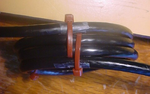
You should place an RF choke, in the feed line right at the feed point of the antenna. You can make an effective choke by using the coax that connect to the antenna.

Mark of a length of about 27 inches close to the antenna feed point. Make a flat coil, that is with the turns of the coax side by side, so that the two marks that you made end up across from each other. Secure the turns of coax so that they stay flat and next to each other.

The will make an effect RF choke for the FM band.

From Brian Beezley's web page.

balun3.jpg


This will help prevent noise that is picked up by the outside of the shield of the coax from being able to flow on the inside of the shield of the coax to your tuner. It will also help decouple the feed line from the antenna and help prevent the feed line from skewing the radiation pattern of the antenna.

That said, the elements of the antenna will do what antenna elements do, they will pick up any noise that is close by.

It is a bad idea to place an antenna close to anything that may be a source of noise.

If an antenna is placed in proximity of other conductors it will detune, that is change the design frequency of the antenna and skew it radiation pattern and reduce the signals that your are trying to receive.

In general it is recommend that the elements of an antenna be at least a full half wave length from other conductors.

If the antenna elements are close to a noise source they will not only respond to the E-field of the noise source , but also the H-field.

The issue with one of your stations being received at more than on frequency is likely to be caused by what is called fundamental overload.

That is the signal is strong enough to overload some parts of the tuner and that will cause the signal to appear at more than one place on the dial.

It may also make your receiver less sensitive to weaker signals.

Is the alignment of the tuner section of your receiver up to snuff as we used to say? A touch up of the RF front end of your tuner might help a little.

Is this one of the Techniques models that has a wide narrow IF selectivity option? If so, it may work better in the narrow mode, although fidelity may suffer.

If you want to explore another option, a well designed helical resonator filter might be able to attenuate your offending station and that might, along with proper antenna installation, improve the performance of your receiver.

Antenna relocation and orientation may help with all of your issues.

Again, after proper antenna design, it is location, location, location and orientation for antennae that have directional characteristics.

Try to keep the antenna elements as far away from other conductors, metal objects and noise sources as possible and orient it for the best reception of your weakest signals.
 
Very informative, as always big guy! I have already done some of what you're saying and I'll try the rest out on Mon.

Any thoughts on Q1?

Tyler
 
Last edited:
"1. One of the stations that I listen to is a college station across the street from my school and it is a strong signal. I have noticed that I hear it on its assigned 89.7 but also two spots just above that (highest one is at about 90.5-ish). By rotating the dipole around, I can eliminate the two ghost images. Why does this occur- the freq shift? It does not seem to be a harmonics-thing. And I don't think that multipath interference can cause alternate freq ghost images, correct?"

"Any thoughts on Q1?"

Yes, as I stated in my previous post, it is likely due to fundamental signal overload of the RF front end of your receiver due to the signal strength of that station.

"The issue with one of your stations being received at more than on frequency is likely to be caused by what is called fundamental overload.
That is the signal is strong enough to overload some parts of the tuner and that will cause the signal to appear at more than one place on the dial.
It may also make your receiver less sensitive to weaker signals.
Is the alignment of the tuner section of your receiver up to snuff as we used to say? A touch up of the RF front end of your tuner might help a little.
Is this one of the Techniques models that has a wide narrow IF selectivity option? If so, it may work better in the narrow mode, although fidelity may suffer.
If you want to explore another option, a well designed helical resonator filter might be able to attenuate your offending station and that might, along with proper antenna installation, improve the performance of your receiver.
Antenna relocation and orientation may help with all of your issues."


When you move the antenna, you reduce the signal strength of that station below the the threshold where it is a issue.

The frequency is not being shifted, in basic and but not completely accurate terms, it is just "leaking through" the tuner section of your receiver due to the strength of the signal.

That is why I mentioned the option of a high quality helical resonator filter to reduce the level of the that station. This type of filter is quite selective, but it does exhibit some insertion loss.

You would install it right at the antenna terminals of your receiver.

Proper antenna design, location and orientation may go a long way to improving your reception.

All this being said, a different receiver may perform better in your RF environment, just due to a different design of the RF front end.

First step is to redesign your antenna and experiment with various locations and orientations of the antenna.

Good luck with your signal hunting...:D


BTW, thanks for the latest information on Voyager in the other thread. You are sharing some great information.

You just need one of the Dish Antennae from the VLA on the roof and your FM reception problems would be solved...:D:D
 
Last edited:
Hey, in studying your first post, I realized that the coil choke needs an inexact, but ballpark diameter for the inductor to work at the 90MHz range. The pic looks like that's about 3". Is that about right? I do not know the descriptive mathematics for it. And you're also showing 3 coils at that diameter.

Could you also give me an exposition on why the choke works here? I would assume that the issue is dealing with the B-field, correct?

Thanks-
Tyler
 
G'day mate, a choke balun of this type is relatively non-critical as the coil 'choking impedance' just needs to be sufficiently large for effective operation at the operating frequency.

A balun of this type is more correctly called a 'common mode' RF choke, but it does perform very effectively as a balun. This type of balun blocks the flow of unwanted 'common mode' antenna currents and allows only the intended correct antenna currents to flow.

They are a complex subject. More detail is in here: http://audiosystemsgroup.com/RFI-Ham.pdf Regards, Felix (vk4fuq) aka catman.
 
Hey, in studying your first post, I realized that the coil choke needs an inexact, but ballpark diameter for the inductor to work at the 90MHz range. The pic looks like that's about 3". Is that about right? I do not know the descriptive mathematics for it. And you're also showing 3 coils at that diameter.

Could you also give me an exposition on why the choke works here? I would assume that the issue is dealing with the B-field, correct?

Thanks-
Tyler

Felix, thanks for the link, I was looking for it in my saved places.

Your estimate of the diameter is probably close. I don't worry about the diameter when I make a coaxial choke, because as you know it is the length of the section of coax that you use that is important.

The 27 inch specification is roughly a quarter of a wavelength of coax at the frequency of interest, taking into account the velocity of propagation of the coax used.

Length of coax in feet for the coaxial RF choke = (234/Freq in MHz)x Velocity Factor.

The velocity of propagation for RG59 coax, depending on manufacturer is about 0.82 to 0.86.

The two pieces of tape on the coax in the picture represent the marks that indicate the length of 27 inches and as long as the construction technique is followed the diameter takes care of its self.

After that as you can see from the picture below, it in basic terms it is just an parallel resonant RF choke.

That is in basic terms the RF or noise that is on the outside of the shield of the coax encounters the coil of coax, which in electrical terms is functioning as a parallel resonant circuit, relative to the outside of the shield of the coax, it does not affect the signal flowing in the coax. The high impedance of this parallel resonant circuit (the coil of coax) blocks the flow of RF.

In theory, when at resonance (inductive reactance and capacitive reactance are equal), a parallel resonant circuit has an infinitely high impedance.

In general form, for a parallel resonant circuit z= 1/(Z1-Z2). When the impedance of of the inductive reactance and the impedance of the capacitive reactance are equal, the impedance of the choke is, ideally, infinite.

It is the high impedance relative to the outside of the shield of the coax that helps prevent the flow of RF on the outside of the shield of the coax.

What happens without a means to decouple the coax from the antenna, any noise that is picked up by the shield is coupled into the antenna element that is connected to the shield and then is able to flow down the inside of the shield to the receiver.

There are other more complex methods of decoupling the feed line from the antenna as can be seen in the PDF in the link supplied by Felix.

This method is simple and easy to implement as it requires nothing more than the feed line itself.

I have kept my explanation rather simple for those without the background that Felix and I have and to the point of Tyler's questions.

I have added a second picture that shows the flow of feed line current when a balanced antenna is fed with an unbalanced feed line.

This picture represents a transmitting antenna, so in Tyler's case, a receiving antenna, the current flow, noise picked up by the feed line, the current (noise) on the outside of the coax would be flowing in the opposite direction. The arrows would be pointing upwards.

All of this being said, the noise that is picked up by the feed line may not be a large issue in all cases. But this is so easy to implement, it is good insurance.
 

Attachments

  • COAXIAL FEED LINE CHOKE SCHEMATIC REPRESENTATION.JPG
    COAXIAL FEED LINE CHOKE SCHEMATIC REPRESENTATION.JPG
    42.2 KB · Views: 45
  • FEED LINE CURRENT FLOW DIPOLE ANTENNA.JPG
    FEED LINE CURRENT FLOW DIPOLE ANTENNA.JPG
    22.2 KB · Views: 48
Last edited:
and the antenna up at the ceiling near fluorescent fixtures.....
try turning the light off and see if it makes a difference . i know it does in my workshop .
also try an outside antenna for best results .
 
Hey Pete,
I have tried lower in the room with too much attenuation- ceiling level seems to be best for signal strength. An outdoor antenna may not be possible.

JBL,
The second pic that you added, that's what I have done. The arrows- do they indicate current direction at some instant? And at the bottom, is that symbol off to the right a ground? I have mine connected to the coax clamping mechanism as one of the 75 ohm terminals.
 
Hey Pete,
I have tried lower in the room with too much attenuation- ceiling level seems to be best for signal strength. An outdoor antenna may not be possible.

JBL,
The second pic that you added, that's what I have done. The arrows- do they indicate current direction at some instant? And at the bottom, is that symbol off to the right a ground? I have mine connected to the coax clamping mechanism as one of the 75 ohm terminals.

I should have said signal flow. Of course the RF signal is an AC signal.

The arrows represent net signal flow, for the sake of illustration.

The shield of the coax is reference to ground.

We consider that the signal from the antenna flows down the coax to the receiver. Technically a voltage is generated in the antenna from the E-field of the RF signal.

This voltage is impressed on the coax and arrives at the antenna terminals of the receiver. Since the receiver antenna input represents a finite impedance, an alternating current at a radio frequency flows in the antenna input circuit.

The RF choke at the feed point may or may not help in your situation, but there is no reason not to try it if you have enough coax. It is good engineering practice.

If you were to place your antenna outside, it might make your fundamental signal overload issue worse.

There will be nodes and anti-nodes relative to the RF field strength of the signals that your are trying to receive. The strength of the signal that your antenna picks up, may depend on the location of your antenna relative to these nodes.

I meant to ask this earlier, Is your antenna broadside to the direction to the weak station that you would like to receive?

Below is the radiation or reception pattern of a dipole antenna.

The proximity of other conductors will skew the pattern and detune the antenna, reducing its ability to receive signals.

Is the ceiling a drop ceiling with a metal support framework and if so, is the antenna strung across the supports? Do you have any idea of the location and direction of the wiring that is going to the lights?

If you are are able to mount the antenna in a relatively free location, you could try add and element to the dipole antenna, turning it into a two element wire beam. You could gain some signal strength in the direction that the resulting antenna would be pointed. If you have the room on the ceiling, you could even make it a three element beam.

The elements would just be straight pieces of wire spaced a fraction of wavelength from and parallel to the dipole. Technically the addition of the extra element would change the feed point impedance, but the gain in signal might be greater than the loss from the mismatch. There are methods to match this change in impedance to the feed line.

If you do this, it would be a good idea to incorporate the RF choke in the feed line.

An advantage of wire beam antennae is that they are almost invisible.

Such an antenna would be directional and would need to be pointed at the weak signal station of interest.

I am not sure how much effort you are willing to put into this endeavor.
 

Attachments

  • DIPOLE RADIATION PATERN.JPG
    DIPOLE RADIATION PATERN.JPG
    15.1 KB · Views: 26
IMO receiving antenna design isn't as fussy as transmitting. Location is everything. I think most FM stations are vertically polarized so the antenna should probably be vertical, not horizontal. Unless it works better that way. Check the coax losses at 88-108 MHz and compare it to the RG-6 stuff. You may be able to pick up a bit of signal by changing coax if the run is long.
 
Tyler, if you have the real estate on the ceiling and you if you can mount the antenna in the clear, a rhombic antenna cut for the FM broadcast band will supply you with some gain over a dipole. but it will be horizontally polarized.

What is the frequency of the weaker station that your are trying to receive.

What are its call letters and where is it located, I can pull the antenna information for the stations that your are trying receiving and post the information.

Below is an example I just pulled at random from the FCC data base for an FM broadcast station. Notice that the ERP, effective radiated power is the same for both vertical and horizontal polarization, 97.7 kw. The picture is rather small, click on it to view a larger picture.

This was for a station above 92 MHz. I checked a couple of stations below 92 MHz and they were vertically polarized.

IIRC, FM stations on the low end of the dial were required to use vertical polarization to reduce the chance of causing interference with TV stations on channel 6.

This is why I mentioned antenna orientation several times.

This brings up another reason for the RF choke at the feed point of the antenna. If the station of interest is using both vertical and horizontal polarization, the vertical component received by the feed line may interfere with the horizontal component received by the antenna, reducing the amount and quality of signal available the the receiver.

"IMO receiving antenna design isn't as fussy as transmitting."

Contrary to popular believe, the construction of receiving antennae is just as important as for transmitting antennae.

The physics of antenna design does not change.

This myth has come about in the general population, because most of the population is no longer rural, lives in strong signal areas and is not interested in receiving distant stations.

And the general population has no knowledge of antenna design or any method to measure the actual performance of an antenna, other than does it receive the station of interest and since most are in strong signal areas, just about anything will receive their stations of interest.

Correct antenna design is especially important when trying to receive weak signals. The increase in signal strength and signal quality available from a correctly designed antenna may just be enough to drive the tuner into its region of full quieting on a stereo signal.

That means that the signal is strong enough to overcome the internal noise of the tuner, what we call noise and hiss.

My response is to Tyler's question regarding weak signal reception.
 

Attachments

  • ANTENNA POLARIZATION FM BROADCAST FCC DATA BASE.JPG
    ANTENNA POLARIZATION FM BROADCAST FCC DATA BASE.JPG
    16.5 KB · Views: 25
Tyler, if you have the real estate on the ceiling and you if you can mount the antenna in the clear, a rhombic antenna cut for the FM broadcast band will supply you with some gain over a dipole. but it will be horizontally polarized.

What is the frequency of the weaker station that your are trying to receive.

What are its call letters and where is it located, I can pull the antenna information for the stations that your are trying receiving and post the information.

It is WKHS 90.5 in Worton, MD

ERP 17,500 watts
HAAT 66 meters
Class B1
Facility ID 6057

Found this
http://transition.fcc.gov/fcc-bin/fmq?call=WKHS

and this
http://www.radio-locator.com/info/WKHS-FM
WKHS_FM_LU.gif


I am trying to receive in Towson. My reception is great at home (10 mi east of Towson).

Thanks for your contiuuing advice, JBL
 
IMO receiving antenna design isn't as fussy as transmitting. Location is everything. I think most FM stations are vertically polarized so the antenna should probably be vertical, not horizontal. Unless it works better that way. Check the coax losses at 88-108 MHz and compare it to the RG-6 stuff. You may be able to pick up a bit of signal by changing coax if the run is long.

Thanks Conrad. My coax feed is only about 2m.
 
I meant to ask this earlier, Is your antenna broadside to the direction to the weak station that you would like to receive?
Yes. The strange thing is that if I put one end of the dipole up under one of the ceiling tiles and let the other dangle (so hanging vertically and thus always broadside to station), so far, reception is best. The dipole is cut so tuned to 90MHz (78cm/side). But hanging vertically, it is not a full-length dipole in physical end-to-end dimension (it's shorter)- the dangling side just curls down toward the floor; but the wire lengths are unchanged. All of this is against a cinder block wall.

Is the ceiling a drop ceiling with a metal support framework and if so, is the antenna strung across the supports? Do you have any idea of the location and direction of the wiring that is going to the lights?
Yes, it is a metal channel-type and I have placed the dipole ends so that they are held under tiles at that point but with some overhang so that the wire is not in contact with the metal support channels. But the wire is adjacent to the framework.

Tomorrow, I will look to see the orientation of the wiring above the tiles.
 
Last edited:
Yes. The strange thing is that if I put one end of the dipole up under one of the ceiling tiles and let the other dangle (so hanging vertically and still broadside to station), so far, reception is best. But this is not a full-length dipole either- the dangling side just curls down. All of this is against a cinder block wall.


Yes, it is a metal channel-type and I have placed the dipole ends o that they are held under tiles at that point but with some overhang so that the wire is not in contact with the metal support channels. But the wire is adjacent to the framework.

Tomorrow, I will look to see the orientation of the wiring above the tiles.


Tyler, nothing strange about what your are experiencing.

The ends of the elements of a half wave dipole are the high impedance points of the antenna, that means that proximity (in general within one half wavelength) to other conductors, wiring or the framework for your ceiling, may detune and degrade the performance of the antenna.

Another possible issue, the metal framework and or wiring will act as an antenna and may re-radiate the FM signal causing unusual nodes and ant-nodes in the field strength of the RF field (similar to the reflector and directors of a Yagi-Uda antenna), especially if your antenna is in close proximity to the framework and or wiring. You have support members running at right angles to each other, so it might be difficult to predict the RF field strength an a particular location.

With enough experimentation, this might be able to be used to your advantage.

Letting the antenna hang down vertically moves the antenna elements farther away from the metal of the ceiling supports and especially the end of one of the elements.

And your station's signal is polarized both horizontally and vertically, see below.

And contact is not needed to affect the operation of the antenna since it is RF.

For the antenna to perform at its best, the elements need to be straight.

You station uses both horizontal and vertical polarization. See picture below for the engineering details for the antenna in use at your station.

Use the antenna orientation that performs the best for your location.

Another question, how much space is available above the ceiling tiles?
Would it be possible to install the antenna above tiles and away from the wiring and or the ceiling support?
 

Attachments

  • WKHS ANTENNA  POWER INFO.JPG
    WKHS ANTENNA POWER INFO.JPG
    15.9 KB · Views: 16
Damn, you are sooooo good at this. I am learning a LOT in this thread. Thank you for that.

I am on the first floor and above the tiles is the metalwork support trussing and I don't think that it would be good for an antenna location. The underside of the floor above me (above my drop ceiling) is steel/iron sheeting.

I will not be able to easily separate the antenna or its ends one half wave from the drop ceiling crossmembers. I will try suspending the dipole from threads dropping from the crossmembers in the morning.

What I can tell you is that at cell frequencies the building is a Faraday cage, indicating that there is lots of metalwork throughout.

I don't understand to what you are referring with
And contact is not needed to affect the operation of the antenna since it is RF.
EDIT: Never mind, I got it.

Tyler
 
Last edited:
]"I don't understand to what you are referring with

And contact is not needed to affect the operation of the antenna since it is RF."

"The ends of the elements of a half wave dipole are the high impedance points of the antenna, that means that proximity (in general within one half wavelength) to other conductors, wiring or the framework for your ceiling, may detune and degrade the performance of the antenna."

This was in response to your statement that there was not any contact from the antenna to ceiling support structure.

Below is the voltage and current distribution for a half wave dipole. Maximum current at the center (75 Ohm feed point, lower impedance) and maximum voltage at the ends, (higher impedance). For the voltage to be at maximum, the impedance is at maximum.

At RF frequencies or any frequency for that matter, the higher the frequency, the lower the impedance of a capacitive circuit. In this context the greater the effects of the capacitive coupling between the antenna elements and the adjacent conductors, wires and or the ceiling supports.

All things being equal, if we were talking about power line frequencies or even audio frequencies, the affect of the capacitive coupling would be much lower.

The effects of capacitive coupling of adjacent conductors to the high impedances (the ends of the dipole) in greater, therefore electrical contact and even physical contact is not needed for there to be interaction.

That is not to say that there is not some interaction along the full length of the dipole, but is is greater the closer that you get to the ends of the dipole.

Any chance of getting your antenna close to an outside window, preferably broadside to your station?

You could take a fiberglass rod or a broomstick and attach your antenna to it, (it needs to be none conductive) keep the antenna elements straight and inline . Make a handle and use it to look for a "hot spot" in the RF field for your station of interest.

You want to keep the antenna away from your hands and body, and the feed line should stay close to perpendicular to the antenna.

I use a device similar to the one shown below, but more accurate, to measure RF field strength. I have a calibrated LNA to use ahead of it for weak signals.

Removes the chance of damage to my portable spectrum analyzer.
 

Attachments

  • DIPLOLE ANTENNA VOLTAGE AND CURRENT.JPG
    DIPLOLE ANTENNA VOLTAGE AND CURRENT.JPG
    25.8 KB · Views: 16
  • B+K430 CATV FIELD STRENGTH METER.jpg
    B+K430 CATV FIELD STRENGTH METER.jpg
    60.9 KB · Views: 20
BTW, if you do have access to a small diameter fiberglass dowel, the length of your antenna, you can mount the antenna to it and use it to hang the antenna in what ever orientation that gives you the best reception, keeping the antenna element fully extended and straight.

Or if you use two pieces of fiberglass doweling you could make a rigid wire V beam antenna.

You might even try both a quarter wavelength and a half wavelength single piece of wire connected directly to the antenna terminals of your receiver.

At this point it may be all about experimentation.
 
Last edited:
Back
Top Bottom