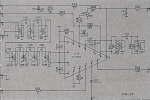
Nikko NT 950 Tuner, no stereo, low level mono output.

I have put back IF coil back and get mono output only, while voltage on the pin 6 has stayed higher 3.6V compared to previous 1.8V.
Voltage on the TP2 is still dead on 5.6V
I have also changed main PS cap and few more, so in order to know what I am doing it is necessary to change them all.
There is a something like wax in the IF coil slug and on some places I can see tiny wire.
Is there proceed for safety turn it?
 
You've got a tough one there. Does the voltages on pins 15 & 16 change with signal or no signal?

The voltage you are measuring on TP2 is so far off that I don't think physically tuning the coil will make any difference, particularly since adding a capacitor did not make any difference. You may end up damaging the coil if you try too hard. You earlier measured 0.9 ohm across the coil, so I don't think the coil is open. I've attached the typical pin voltages for the chip from the data sheet, and many of what you measured are quite a bit different.

At this point, I am going to suggest you replace that LA1235 IC. If you are in the US, the best deals I could find were:

Screenshot 2024-03-27 100107.jpg
 
You've got a tough one there. Does the voltages on pins 15 & 16 change with signal or no signal?

Same old...No changes with/out signal, bur now pin 16 is 3.2V, pin 15 0.65V.
Output level gets on normal when I touch pin 9 with probe, like before as a special issue.
There is a bunch of 10 micro farads el cap around PS IC with correct values, bit after 20 years it is just a junk.
Does some IC inside has separate blocks. so it could be partly working or some variations of voltage could cause partly faults?
I am from Serbia, nothing here grows up in nature like LA1235.
I have also IF coil from old hard sounded Dual tuner, it is for similar CA3089.
Does it possible to make Frankenstein Dunniko?
Connections of the IF coil are on the same pins 8,9,10.
 

Attachments

  • Opera Snapshot_2024-03-25_194652_archive.org.png
    Opera Snapshot_2024-03-25_194652_archive.org.png
    737.3 KB · Views: 0
I am measuring 17.5kOhm R121 what could be explanation to have that 5.6V across, what is TP2 reference voltage.
In the service manual R121 is listed twice, with 6.8kOhm and 18kOhm.
I did not find any trace of earlier repairing attempt, so is that doubled values is for different IF coils?
 

Attachments

  • Opera Snapshot_2024-03-28_162138_nikko_nt-950_tuner.pdf.png
    Opera Snapshot_2024-03-28_162138_nikko_nt-950_tuner.pdf.png
    33.3 KB · Views: 1


Now listening audio signal directly from pin 6, LA1235.
There is no signal when muting is switched off, so it will be good to know how switching works in order to find out where is the fault.
So the signal is coming to the stereo decoder LA3401, but there is no decoding
 
Measuring 8V on to pin 5 (signal from LA1235) instead of 3.2V according to data sheet for LA3401.
I will test triggering stereo and performance with different values of components from data sheet.
 

Attachments

  • Opera Snapshot_2024-03-30_175307_LA3401.PDF.png
    Opera Snapshot_2024-03-30_175307_LA3401.PDF.png
    154.2 KB · Views: 2
have changed el cap C121 on the pin 9 and finally get 0V on the TP2 with paralleling caps to IF coil, across R120.
Muting is working now, but there is no signal for stereo even when muting is on and I can hear output signal when strong signal is present, opposite to weak or no signal case, when muting is activated and there is no signal on the output.
Automatic scanning working too now, what means that detection is activated, but I am not sure does it stop when stereo signal is detected only.
 
C121 is on pin 10. TP2?? I thought we confirmed that the voltage across R121 is measured at TP1. I can not find any reference to a TP2 in the manual. WE NEED TO BE MEASURING THE VOLTAGE ACROSS R121. Before we go any further, let's confirm the detector is working.

With the receiver tuned between stations, measure the voltage across R121 (TP1). Post the result:
Find a strong station and tune the receiver so that it is centered on that signal the best you can. Measure the voltage across R121 (TP1). Post the result:
Now tune slightly below the center of that strong station - not off the station, but just slightly below center. Measure the voltage across R121 (TP1). Post the result:
Now tune slightly above the center of that strong station - not off the station, but just slightly above center. Measure the voltage across R121 (TP1). Post the result:
 
It is 0.2V centered to strong station, up a bit 0.04V and down 0.08V.
It is TP1, across R121 ,my mistake.
Output signal is weak, almost has a level of noise.
C121 is on pin 10, right.
No signal from any station has 0.0V on TP1.
 
Last edited:
Added 20% more capacity and there is constant one frequency noise on to station without sound and ordinary noise between station with constant 0.4V on to TP1.
Decreased capacity and now is 0.7V on the strong station and 0.8V between stations.
Is voltage raising on the TP1 between stations and it is 0V tuned on to station when detector is aligned?
Reached 0.11V on to TP1 with strong signal tuned and 0.15V with no or weak signal.
There is a point when voltage on the TP1 drops near OV, but output signal gets weak covered with background noise.
I have to get more caps of smaller caapacity.
 
Last edited:
The detector is properly tuned when it is tuned to the center of the IF bandpass (10.7 MHz). When the receiver is receiving only noise, that noise will of necessity be centered in the IF bandpass and the voltage across R121 should be zero. When you are tuned to a strong station, and you have that station centered in the bandpass, again, the voltage across R121 should again be zero. When you tune slightly off center, the station is no longer in the center of the bandpass and the voltage will be a bit above or below zero.

You currently have an offset of about 0.15 volts, so the FM detector is not tuned exactly in the center of the bandpass. The fact that the voltage at that point goes up and down as you tune across a station would indicate that the detector is probably working properly. Try to find a value of capacitor that gives you as close as you can get to zero volts at TP1 when you are tuned to just the noise between stations.
 
Thanks for that. Probably I have overshoot it with capacity and get that noise instead of sound while signal was strong right on the station.
I will get a trimmer cap, it is sensitive and picking up interference's like sponge. Even touching TP1 pins with probes makes mess and with three pin interface for measuring voltage also was impossible to do anything.
There is also possibility to adjust sensibility of stereo decoder on to LA3401 and like here distortion dynamics, level of output signal.
Maybe those components around LA3401 also has gone out of specs.
 
Perhaps the LA3401 does have problems, but it makes no sense to move on to the stereo decoder until the detector is working properly.
 
One thing I have to understand before start with trimmer cap.
At one moment there where OV on to TP1 but sound was very weak drowned in to noise, despite tuned strong signal right on the station.
 
You said that when you were tuned to the center of a strong signal, you saw about 0.15 volts on TP1. If you then tuned the station so that you saw zero volts at TP1, then you would be tuned quite a bit off the center of the station. Being tuned off center will cause the reception to become noisy.
 
There where weak sound despite tuned right on to strong station followed with usual flat noise of out of any station like with voltage on to TP1 close to zero what I understanding as to much capacity added across R120 or it already means that IF coil is damaged?
That tuning zero volts on to TP1 with paralleled capacity is not linear and I was also measured pin 7(connected to one on the TP1 that has voltage change) in reference to the ground which has voltage now 3.6V where is the level of output signal strong and also with minimal distortion and noise.
It is about -2.5V on to TP1 and when is difference to zero is positive, output signal gets weaker followed with noise.
Maybe this results helps to detect fault.
 
Last edited:
When you get a chance, again measure the voltages on all the pins of the LA1235 to ground and post. Measure when tuned to the noise between stations.
 
1-3. 3V,
4-5. 0V,
6. 1.9V,
7. 11.9V, (7.29V)
8-10 6.3V
11. 13.5V
12. 6.25V,
13. 3.1V, (3.8V) --------- 2.8V
14. 0V
15. 6.8V, out of station 5.21
16. 3.45V out of station 6.2V


Pin 7 and pin 13 has changed voltages after getting -2.5V on to TP1.
Values on the right side is for tuned between station, no signal.
 
Last edited:
When you tune slightly off center, the station is no longer in the center of the bandpass and the voltage will be a bit above or below zero.
Confirmed at 0.05V on to TP1 after adding more than 500pF across R120. .
Also LA1235 is less hot, but sound is weak again followed with noise.
There is no difference in sound when switching muting off-on, no stereo but muting low signals is working.
 
Last edited:
Those voltages are so far off, it almost has to be a bad IC. I think you are going to have to find and replace that LA1235.
 
Back
Top Bottom