• The move to the new server is done. There are some software and database maintenance updates in process. This has us passing the hat around to help out. We appreciate any donations. Seriously, even a dollar helps. The payment page may be found here - https://www.audiokarma.org/support.html

Audiowind A-300 Phono Preamp 'build' and questions

JoeDotCom

Super Member
Hi DIYers!

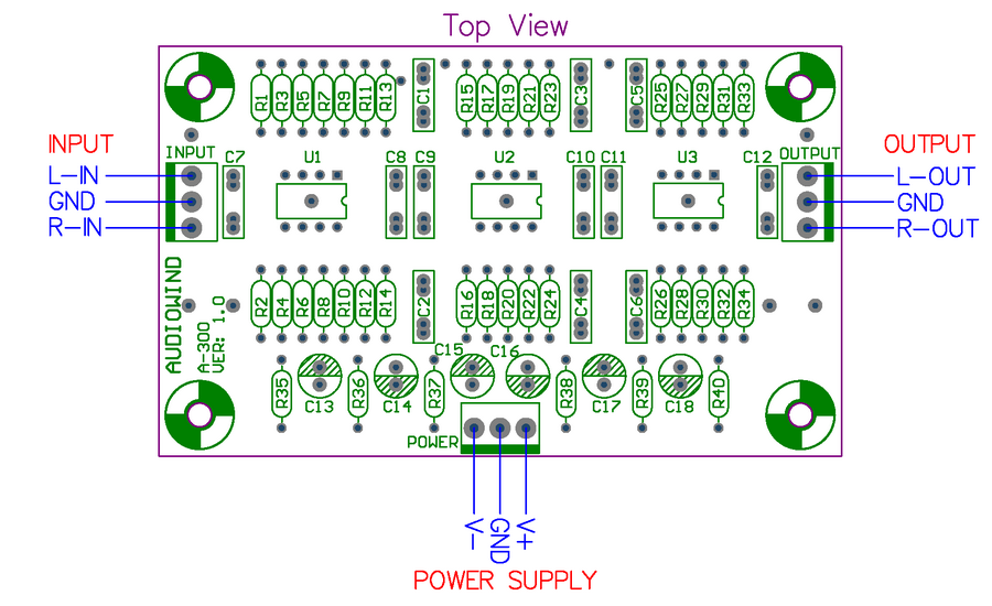
I picked up a Audiowind A-300 Phono Preamp off of ebay in an attempt to put together an inexpensive phono preamp. $25 on ebay, another $10 at radio shack, plus scavenging some parts I have piled up... off I go.

I setup two 9v batteries in a +/- 9v configuration like in HypnoToads graphic:
Batteries-1.jpg
(from http://www.audiokarma.org/forums/showthread.php?t=395898)

Positive and negative leads run to a dual pole switch then to the module, the ground goes straight to the module.

i also added an LED across the + and - leads after the switch (radio shack part number 276-0270). the Led comes w/ an 680 ohm resistor built in. (I think I want to increase that resistor to something more like 6-8K at some point.

anyway, I have a case for the unit, it is an old Camera Control Unit that i scavenged. I don't have the board installed in its final location yet, so it is all just thrown together at this point. (i am a bit embarrassed to share the pics).


On to my question / plea for help....

Everything powers up OK and things sound good on my "sacrificial" system. noise is equivalent to the built in phono input on the receiver, however there is a noticeable amount of hum when i crank the volume up with no music playing. (with music on, the hum is inaudible). Also, i read in HypnoToads thread that there should be NO voltage present on the RCAs... i measured mine and the inputs are at zero.. however, I have 9mv on the left and 2mv on the right outputs. Is that bad? I looked over my wiring and i think I did it all right (ugly as it is)... did i connect something wrong?

6317d186-d441-1c83.jpg
 
Register to hide this ad
here are the rest the photos I've taken... because I know you want to see. :)

6317d186-d472-bdbe.jpg


6317d186-d481-a781.jpg


6317d186-d48c-2b68.jpg


6317d186-d499-2733.jpg


a6898e0d-7b4c-aae4.jpg


6317d186-d4a4-ca77.jpg


6317d186-d4b5-e9b0.jpg


6317d186-d4c2-ba9e.jpg


Sent (and possibly poorly text-to-speech transcribed) from a mobile device.
 
Last edited:
just for fun, here is the info from the ebay listing:
vendor: "electronics-salon" (not affiliated)

This item has been assembled, and electrical test passed.

Best Operating Voltage: +/-9V DC to +/-15V DC.
Gain: 40dB.
Input Impedance: 47K ohm.
Output Impedance: 330 ohm.
RIAA Accuracy: <1dB.
Bandwidth: 20 to 100KHz (-3dB).
Distortion: 0.05% (@1KHz).
SNR: >68dB(use batteries supply).
Size: 100 x 60 x 16mm (L x W x H).

Used high-quality electronic components:
Thickness 1.6mm FR-4 fiber glass PCB (double layer).
HQ terminal blocks easy connection wire.
Polyester film and metallized film capacitors.
Precision 1% metal film resistors.
Ultra low noise and low distortion audio OP AMP OPA2134PA.
Gold-plated OP AMP IC socket, can easily replace other OP AMP.

Module Spec.:
http://www.audiowind.com/pdf/A-300.pdf, No paper specifications, please download this document.

Other, if you need power supply module and power transformer, we recommend these items:
Power supply module (regulator):
Low Noise +/-15V Regulator, for Audio Preamplifier.
Power transformer:
Toroidal Power Transformer, 15VA, P: 115/230V, S: 2x18V
A-300CON.png


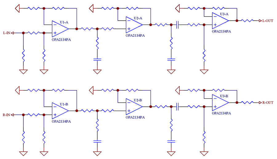
A-300OPA2134SCH.png
 
Just a few things to consider:

Measure your batteries to see if they have the same voltages, if they are noticeably different that can cause DC offset AFAIK.

Also that circuit does not have DC blocking caps at the outputs, this is good and bad, the less caps in the circuit the better, adding them may affect the sound quality. But the good is they will block any DC.

Also swap the op amps around, some have more DC offset than others, even though they are the same op amps it varies.

What are you plugging it into? Most preamps have DC blocking caps at the inputs.

With the hum, are you using your turntable ground connected to the ground on the PCB?
 
Just a few things to consider:

Measure your batteries to see if they have the same voltages, if they are noticeably different that can cause DC offset AFAIK.
I read that in a previous thread, I believe from you. :) I did that, and batteries match. They're both putting out a little more than 9 volts. and if I measure plus to minus, I get a little more than 18 as expected.


Also that circuit does not have DC blocking caps at the outputs, this is good and bad, the less caps in the circuit the better, adding them may affect the sound quality. But the good is they will block any DC.

Also swap the op amps around, some have more DC offset than others, even though they are the same op amps it varies.

What are you plugging it into? Most preamps have DC blocking caps at the inputs.

With the hum, are you using your turntable ground connected to the ground on the PCB?

how much dc voltage is dangerous / detrimental to the sound? Is 9ma unsafe?

I will try swapping the opamps , will just end up just moving into extra dc current 'into' the circuit more?

currently I am using it on a silver faced marantz receiver, though, my ultimate goal is to run it on my 'chi-fi' Grant Fidelity 2a3 tube amp, which does not have a phono section.


as for the hum, it really is not noticeable, although if I jack the volume up very high I can tell it's there. It is not noticeable at normal levels.

I was not sure what the best way to setup the ground is. should I connect the ground from the batteries to the chassis, and also connect the phono ground to that same chassis screw?

thanks again for reading, and your input. :)
 
You may just have an op amp with high DC offset, swapping them around may get you one at the outputs with a lot less.

Connect the grounds to the battery ground of the PCB.

If you are still worried, ad this circuit to the output. It will block the DC offset and not interfere with the sound too much.

DCBlocking.jpg
 
Thank you for the reply HypnoToad, I will rework my ground wiring to all stem from the PCBs power supply ground.

Also thank you for the DC blocking circuit diagram.

I am still researching what a typical allowable DC offset is for a line level output. I know from EchoWars' famous Amplifier Distortion, DC-Offset, and You! thread:
"0 - 15mV: Damn good!!"
"16mV - 50mV: An acceptable value"
However, that thread is talking about the output of a power amp. I expect speaker level voltage tolerances are different from line level.

I also found some posts dealing with headphone amps saying that anything under 20mv is acceptable.

I also read somewhere that i may need to provide a higher voltage so I may try running +/- 18v by running 9v batteries in pairs in series.


Also, i contracted the manufacturer and from what i can understand from their reply, I think they are saying that that voltage is expected and OK to use.:

Dear friend,
Tell me Two batteries connection method.
The first battery, Negative connect to V-, Positive connect to GND.
The second battery, Negative connect to GND, Positive connect to V+.

These are original TI OPAMPs, 0 mV DC output is the pursuit of our idealized, however, due to three times high-gain opamp, output cannot be absolutely avoided DC.

Please see the original schematic, help me to continue to check:
http://i891.photobucket.com/albums/ac119/ekevin999/Module/A-300/A-300-1.png

Thank you,
Lily
here is their schematic. I have not seen this more detailed schematic for the Audiowind A-300 Phono Preamp before, so I also copied it to my server for prosperity.
audiowind%20A-300-1.png


Thank you all (especially HypnoToad) for all the knowledge thus far. I will continue tinkering with this and of course report back my results. :)
 
The output op-amp in this design is configured for DC gain of 10 and has a maximum input offset spec of 3mV, so the output could contain up to +/-30mV DC and be 'normal.' I prefer to see phono preamp output offset below 1~2mV, because it appears across the downstream volume control pot. DC on the pot leads to a noisy pot, which is intolerable. I suppose the best solution is to find a chip for U3 that has extremely low offset in both channels, but you might need a big handful to choose from.
 
My 'totally out of control' thread about offset is specifically geared for the discussion of offset at the output of a power amplifier. But, DC at the output of any amplifier stage is undesirable. How much DC constitutes a problem depends on the circuit and how it is used and what it is plugging in to. For this circuit, I'm with Mike...1 to 2mV is where I'd like to be.

The OPA2134P is just 'OK' as far as DC precision. The OPA2132P usually does better. I've also used the AD823, the LME49860, and the LME49720 in applications where I was trying to minimize offset so I could omit an output coupling cap.
 
You may just have an op amp with high DC offset, swapping them around may get you one at the outputs with a lot less.

Connect the grounds to the battery ground of the PCB.

If you are still worried, ad this circuit to the output. It will block the DC offset and not interfere with the sound too much.

DCBlocking.jpg

Awe yah... DC blocking circuit is on the way. :-)

c6e4e367-b9f1-4bf5.jpg


update: Here she is in action. sounds great. thank you to all who helped guide me here. :)

2012-08-09%2023.10.10.jpg


Sent (and possibly poorly text-to-speech transcribed) from a mobile device.
 
Last edited:
JoeDotCom,

What does your AW phono stage look like now? Outside and Inside cabinet shots? Your last picture shows the new parts, I am curious about the circuit you built and the results.

I recently built the AW A-300, I also bought the related power supply and voltage regulator, and a nice audio component style aluminum case. I have some OPAMP's on order and am going to run some chip rolls soon.

Anyway just curious about your completed build and if you solved your HUM and noise issues?

Mine is dead silent. I solved a HUM problem by moving, re-routing the power feeds away from any other wiring. I had bought a 4" x 10" piece of copper from Ace Hardware and it is something I may install just to hear if it makes any audible difference, even quieter I hope? I had gone out and bought the copper and when I opened up my case, I noticed my powering high voltage wires were looping too close to in-coming signal wires and this solved my HUM issue.

I am nearly done with it now, I had a power switch with an LED in it and I accidentally burned out the LED lamp, so I have another on order and when it arrives I now know what to do not to damage this one! I'll post finals when mine is finished.
 
Back
Top Bottom