• The move to the new server is done. There are some software and database maintenance updates in process. This has us passing the hat around to help out. We appreciate any donations. Seriously, even a dollar helps. The payment page may be found here - https://www.audiokarma.org/support.html

Pioneer M-90 Issue- need help.

Matt03221

Active Member
Hello, looking for some help with my M-90. I'm getting good audio out of both channels but also getting what sounds like a 60 Hz hum out of the left channel. It starts right after the safety relays kick in. It's in the headphones and at the speaker terminals and it's not affected by the volume control or input selector switch. Don't know if it's related, but I also noticed the left channel DC offset is a bit higher than what I remember- which is 4mv. Right channel still at 4mv but the left channel is now at 8mv. Any suggestions on where to start would be greatly appreciated!!!
 
Register to hide this ad
original caps inside i.e. has it ever been updated/repaired?

sae-7125- I recapped it back in Oct. It worked fine for a couple of months and then I turned it on one evening and the hum was there. Story on the recap at the AK link...
 
nice amount of photos in your recap thread.

have you tried shorting the amplifier signal input(s) and then listen for hum/noise (speakers or headphones)?
 
*custom active cooling is a nice treat vs factory disposable slow-cooker convection cooling

Completely isolated it from everything- just the amp and speakers and it's still there.
isolation is a good start. any inspection for broken solder joints while the recap was in full swing?

fractured ground connection somewhere can instigate hum. verifying input signal ground can help as well, maybe even utilize contact enhancer fluid/spray.
 
@Matt03221 Just saw this and your other thread. I noticed you had a voltage selector switch let go and you asked if it is a common issue. Yes is the answer. Plenty of them let go- too much spring pressure and nearly 40 years of plastic becoming brittle. You can either scavenge one from an old Pioneer cassette deck or something else with the same selector, but they will all be the same age and likely to fail. Your repair looks pretty good, but I would consider hardwiring the unit to your local voltage and completely bypassing the troublesome voltage selector. Bear in mind, any poor contact in that switch could lead to a fire from internal arcing.

As for your current issue, did you replace all the diodes around the old glue when you cleaned up the board for the new caps? The glue corrosion gets into the glass envelopes of diodes and can cause zeners to go crazy, other diodes to leak or fail, often randomly or due to temperature/current flow.

Basically all the small signal, zeners and other diodes where ANY glue touched them. Even if they look perfectly fine- replace them.

1768720725798.png

Your DC offset is not a problem unless it is wildly unstable.
 
Last edited:
nice amount of photos in your recap thread.

have you tried shorting the amplifier signal input(s) and then listen for hum/noise (speakers or headphones)?
I've not thought to try that but certainly can and report back.
@Matt03221 Just saw this and your other thread. I noticed you had a voltage selector switch let go and you asked if it is a common issue. Yes is the answer. Plenty of them let go- too much spring pressure and nearly 40 years of plastic becoming brittle. You can either scavenge one from an old Pioneer cassette deck or something else with the same selector, but they will all be the same age and likely to fail. Your repair looks pretty good, but I would consider hardwiring the unit to your local voltage and completely bypassing the troublesome voltage selector. Bear in mind, any poor contact in that switch could lead to a fire from internal arcing.

As for your current issue, did you replace all the diodes around the old glue when you cleaned up the board for the new caps? The glue corrosion gets into the glass envelopes of diodes and can cause zeners to go crazy, other diodes to leak or fail, often randomly or due to temperature/current flow.

Basically all the small signal, zeners and other diodes where ANY glue touched them. Even if they look perfectly fine- replace them.

View attachment 3678841

Your DC offset is not a problem unless it is wildly unstable.
Thanks for the comments! I did not replace or even check any of diodes during the recap simply because the unit was working fine prior. However, probably best to go back in there and do that. That was lazy on my part.
 
*custom active cooling is a nice treat vs factory disposable slow-cooker convection cooling


isolation is a good start. any inspection for broken solder joints while the recap was in full swing?

fractured ground connection somewhere can instigate hum. verifying input signal ground can help as well, maybe even utilize contact enhancer fluid/spray.
I tried shorting the inputs with an RCA cable between L and R channels- no change. Can you please share how I can verify input signal ground?
 
RCA cable between L and R channels
i should clarify, shorting plug across + and - of signal input on each channel individually. some older mcintosh and marantz systems used such things for unused signal inputs like phono to reduce system noise consumption from the environment and/or inner chassis stray emf.

Screenshot 2026-01-18 at 15-01-56 mcintosh rca shorting plug at DuckDuckGo.png
a visual example of an electrical modification. chances are the noise will still exist but it helps to reduce all variables.

to verify signal ground with a meter, measure resistance between signal - (rca outer shell) and chassis frame/metal. most vintage gear and a large portion of modern stuff use a common grounding system via the chassis.
 
i should clarify, shorting plug across + and - of signal input on each channel individually. some older mcintosh and marantz systems used such things for unused signal inputs like phono to reduce system noise consumption from the environment and/or inner chassis stray emf.

View attachment 3679305
a visual example of an electrical modification. chances are the noise will still exist but it helps to reduce all variables.

to verify signal ground with a meter, measure resistance between signal - (rca outer shell) and chassis frame/metal. most vintage gear and a large portion of modern stuff use a common grounding system via the chassis.
Thanks do
i should clarify, shorting plug across + and - of signal input on each channel individually. some older mcintosh and marantz systems used such things for unused signal inputs like phono to reduce system noise consumption from the environment and/or inner chassis stray emf.

View attachment 3679305
a visual example of an electrical modification. chances are the noise will still exist but it helps to reduce all variables.

to verify signal ground with a meter, measure resistance between signal - (rca outer shell) and chassis frame/metal. most vintage gear and a large portion of modern stuff use a common grounding system via the chassis.for

i should clarify, shorting plug across + and - of signal input on each channel individually. some older mcintosh and marantz systems used such things for unused signal inputs like phono to reduce system noise consumption from the environment and/or inner chassis stray emf.

View attachment 3679305
a visual example of an electrical modification. chances are the noise will still exist but it helps to reduce all variables.

to verify signal ground with a meter, measure resistance between signal - (rca outer shell) and chassis frame/metal. most vintage gear and a large portion of modern stuff use a common grounding system via the chassis.
Thanks for the additional information! Tried shorting per your instructions but didn't notice any real change. The resistance between the chassis and outer shell if the input terminals settles in at about .5 ohms. CD direct and line direct settle in pretty quick, but the control amp input takes a minute to settle down and has a pretty radical spread rapidly jumping all over the place until it does settle- reading as high as 400+ ohms. I've also poked around a bit with a small diameter wood dowel, but no luck pinpointing a change in the hum. When i get a minute i plan to jump and start checking those diodes john recommended.
 
CD direct and line direct settle in pretty quick, but the control amp input takes a minute to settle down and has a pretty radical spread rapidly jumping all over the place until it does settle- reading as high as 400+ ohms.

That also needs investigation. The control amp input grounds should all be at exactly the same (0V- ground) as all the others RCA outers.
 
That also needs investigation. The control amp input grounds should all be at exactly the same (0V- ground) as all the others RCA outers.
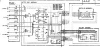
0V or 0ohms? I only tested the inputs between RCA outer shell and the copper chassis with an ohm meter and power off. Looking at the attached it does look like the outer shell is tied direct to ground so odd that the ohm meter doesn't go right to 0.

1769040089222.jpeg
 

Attachments

  • Buffer S.JPG
    Buffer S.JPG
    105.4 KB · Views: 2
So I'm thinker around with it a bit and noticed the heat sinks warming up fight away, especially the left side that has the hum. I know this thing gets warm, but don't recall it heating up that quick and that left side is definitely warner.
 
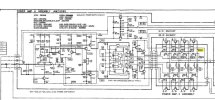
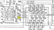
I pulled the left channel amp card out so I could start checking components. I jumped to that vs checking a few voltages as I was afraid to burn up the power transistors. How would I have checked bias as there's no adjustment procedures or checks in the service manual. I notice on the schematic it shows 24mv on the emitter of one of the power transistors- would that be it? Sorry, my circuit theory is minimal.

1769204861263.jpeg
 

Attachments

  • Amp Section.JPG
    Amp Section.JPG
    104.3 KB · Views: 6
Last edited:
*this explains a few things. relying on a chip is easier for the design and manufacturer until it ages in an unpredictable manner and the amp channel nukes itself.

*nice amount of photos

measuring across the output emitter resistor is the usual way of evaluating amp channel bias.
 
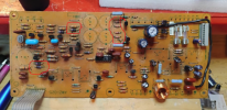
sae-7125, thank you for the additional info. I was working on the card and checked a number of diodes affected by the glue, but all checked good. I did notice R159 did not look right. Looks like it's a 100 ohm and it's got a lower-case f in a circle which I think means it's fusible? It actually reads 136 ohms. Could this be my problem- causing the hum? I have a pick of the actual resistor as well as what one of the undamaged 100 ohm fusible resistors looks like- there are several of the same resistor in there. I checked a couple and they read 100 ohms. Ethier way, I often read fusible resistors should be replaced, but what should I replace these with? Their part number code deal isn't very helpful.

1769370887695.jpeg
 

Attachments

  • FR1.jpg
    FR1.jpg
    115.9 KB · Views: 8
  • FR2.jpg
    FR2.jpg
    64.2 KB · Views: 8
  • R Code.JPG
    R Code.JPG
    88 KB · Views: 9
*info should help with the topic of fusible resistors, it can be messy depending on circuit design. other info around ak and other audio forums can be helpful as well.

if there is a resistor somewhere that is an order of magnitude higher and beyond, it could reduce a circuit grounding strategy (high resistance vs low resistance) and in turn cause noise to propagate within a sub-circuit.

on vintage gear with wire wrap connections even the slightest wire/metal fatigue can reduce conduction therefore introducing higher connection resistance which is a pain to locate... until a wire mechanically breaks off, another headache to inspect for.
 
My plan at the moment is to check a few more components on the card while it's out and then order a metal film resistor to replace the R139 that's out of spec- and anything else I might find. I'd hate to put this all back together and find out that resistor isn't the only issue. It takes some effort to get the card in/out and it really needs to be out to swap components. I'll report back on progress/results.
 
Back
Top Bottom