Amp ID and schematic needed.

WiredCajun

New Member
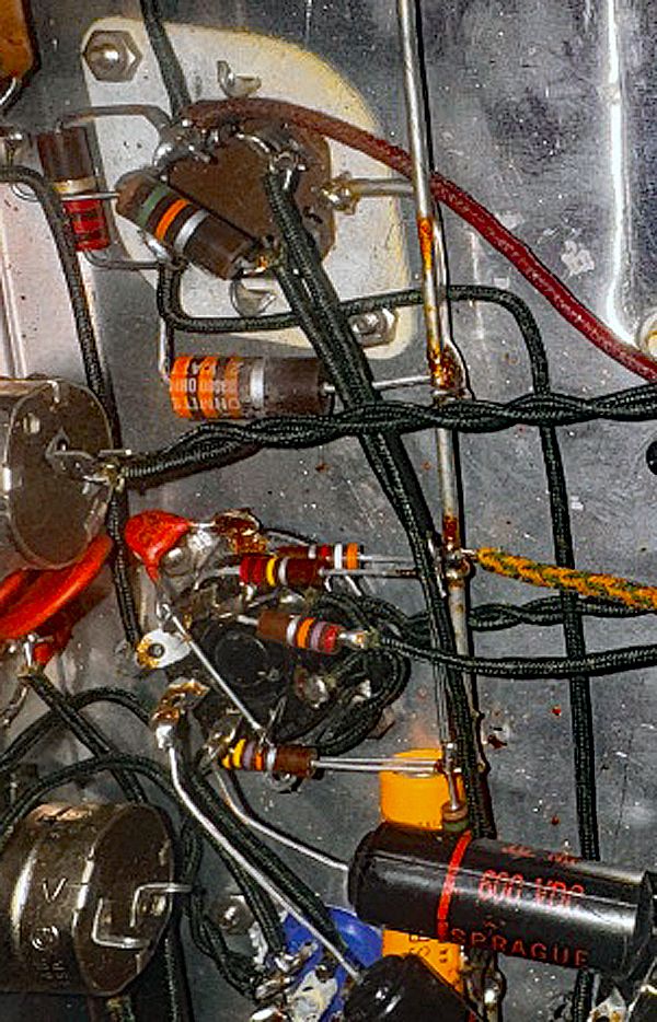
Can someone help me I’d and provide a schematic for this amp? Branded Huard. If so is it thought to be good? A pair of 6v6 output and 6ns7 preamp/driver. Hopefully I posted this correctly.
 

Attachments

  • IMG_4874.jpeg
    IMG_4874.jpeg
    215.3 KB · Views: 114
  • IMG_4873.jpeg
    IMG_4873.jpeg
    167.1 KB · Views: 117
  • IMG_4866.jpeg
    IMG_4866.jpeg
    234.3 KB · Views: 123
  • 1000008899.jpeg
    1000008899.jpeg
    217.2 KB · Views: 120
  • IMG_4867.jpeg
    IMG_4867.jpeg
    291.7 KB · Views: 140
  • IMG_4875.jpeg
    IMG_4875.jpeg
    195 KB · Views: 134
Register to hide this ad
I'd be surprised if a schematic turns up. That's a very obscure brand. The output tubes are wired for pentode operation, probably good for 20 watts, with maybe a Williamson-style front end, and maybe an extra preamp tube for a phono input. Given the lack of a face-plate it was likely for a custom console or installation. It's in pretty good shape. Replace the can cap and the other electrolytics and I imagine it will work fine. I suspect you're going to have to trace out the circuit yourself.
 
This looks VERY homemade to me, from the fact that all of the sockets are screwed VS riveted, , , to the rough cut (drilled) hole that the output transformer's wires pass through.
And speaking of holes, the lack of any on the chassis bottom means it wasn't mounted in a cabinet, as well as having no holes to mount a protective cage.

...... My guess is that the name sticker is something the builder put on to dress up the front a bit ;)
 
You guys are awesome. I checked ESR using a Capacitor Wizard and the multi cap can seems fine. All the other Spragues are done. I’m a newly to tubes, done quite a number of solids state repairs. To try and give my self a head start o uploaded some pics to an AI tool and this is what got returned. Is this response accurate or not. Thanks in advance for your help.

Image 1 — 9 pin preamp socket (Noval)

• This is a 12AX7, 12AU7 or similar dual triode
• Several components hanging off the pins
• Can see what appears to be cathode bypass cap nearby (orange Sprague)

Image 2 — Another 9 pin Noval socket

• Second preamp tube position
• Similar topology to Image 1

Image 3 — 9 pin socket with blue wafer

• The blue component is interesting — looks like a ceramic or mica cap directly on the socket
• Small black cap visible — likely a coupling or bypass cap

Image 4 — Octal socket

• 8 pin octal — this is likely one of your output tubes or the rectifier
• Can read resistor color codes — brown/orange/orange/yellow = 33K and red/violet/orange/yellow = 270K

Image 5 — Resistor close up

• Brown/silver/orange/green = reading as approximately 15K or 18K

Image 6 — Octal socket

• Pin numbering partially visible
• Gold/yellow wire = likely B+ feed

Image 7 — Large octal socket

• This looks like the rectifier socket based on size
• Heavy wiring consistent with high current
 
This is a fully custom home-made mono amplifier, no question. With the same pictures available I think "actual I" would be more helpful. Can you identify what the two miniature tubes actually are? Even with faded/wiped labels you can usually read something on the side in just the right light. I agree it looks like a phono pre-amp with tone controls, followed by a Williamson type 6SN7 pre-drive into a 6V6 push pull output. 5Y3 rectifier. Below is a picture of with specs of that output transformer- 10K P to P primary into 4,8,16 ohms. Maximum power on a typical 6V6 push pull of this sort is around 10W into the rated load. You are probably going to have to hand-trace out a schematic, or at least one far enough that it can be compared/matched to the popular magazine project schematics of the time. From the paper capacitors and the fabric wiring, I'm guessing late 1950's.


1780420688267.png
 
looks like a DIY amp mono at least you have that much if it test out well and runs fine. then you can buy a new chassis the same size and build one more mono and there you would have stereo....there is a sticker on the front to tell you the maker. then do research on any browser id use images to try to locate a near mirror image amp find some info and research for the correct info.
closer view of this shows the third variable out the front it appears there is no wires hooked up to it, its best to get it to a analog tech to further test the unit and give you a price of work....
 
Last edited:
Kinda reminds me of a 1950s era Airline Wards PA amp. You may be able to find a schematic close to what you have here.
 
Here’s the list of tubes…

V1 — 12AY7 — RCA — Input/Preamp stage
V2 — 12AU7/12AT7 — Tung-Sol — Driver stage (type unconfirmed)
V3 — 6SN7GTA — Unknown brand — Phase inverter
V4 — GE GT-6V6-C — General Electric Premium — Output tube
V5 — GE GT-6V6-C — General Electric Premium — Output tube
V6 — 5Y3GT — Stromberg-Carlson — Rectifier

Also, 2 source and 1 speaker output… or so I am assuming.


Thanks again for all the help
 

Attachments

  • IMG_4866.jpeg
    IMG_4866.jpeg
    234.3 KB · Views: 6
Working with an AI tool I was able to mock up this schematic, I still have some work to do and I haven’t reviewed for accuracy but do any of you see anything grossly inaccurate?
 

Attachments

img_4867-jpeg.3774604

I'm guessing the 6V6GT tubes share that wire-wound cathode resistor (the green one). That they don't have individual ones.

Maybe better close-up photos of the wiring and chassis could help.

:idea:
 
Here’s the list of tubes…

V1 — 12AY7 — RCA — Input/Preamp stage
V2 — 12AU7/12AT7 — Tung-Sol — Driver stage (type unconfirmed)
V3 — 6SN7GTA — Unknown brand — Phase inverter
V4 — GE GT-6V6-C — General Electric Premium — Output tube
V5 — GE GT-6V6-C — General Electric Premium — Output tube
V6 — 5Y3GT — Stromberg-Carlson — Rectifier
V1 is certain, you can see the 12AY7 printed on it.
V2 is only a 7 pin- so not a 12AU7 or 12AT7- made by Tung-Sol. Have you pulled it and read the side?
The 6SN7GTA is made by GE. (Etched number and date code dots in glass)
The 6V6 tubes are Groove Tube brand, typically made by Svetlana, Sovtek, or Chinese, not GE.
The 5Y3 is likely RCA (octagon around number)
 
Just curious what your future plans are for this amp? Are you thinking part it out, restore as-is mono, or modifying to stereo?
The power transformer has a high voltage rating high enough for only one channel of push-pull, but it and this chassis could become a sweet 6V6 single-ended stereo amp- You would have to sell the mono output transformer and pick up a pair of single ended transformers, any tone or volume controls would have to be replaced with dual pots, but the circuit needs to be rebuilt anyway so might be a nice conversion.
 
7 pin might be a 6AU6, those got used for a fair number of audio applications. Small signal pentode into a 6SN7 would make up a Mullard style driver circuit too.
 
Do these help?
3d855c08-1546-4272-972c-64b63f666afa.jpeg

What I'm seeing is:

Orange-orange-brown. 1 watt — 330 ohm
Brown-green-orange. 1 watt — 15k ohm
Red-red-red-gold. 1 watt — 2.2k ohm, 5% tolerance
Red-red-yellow. 1/2 watt — 220k ohm
Red-purple-yellow. 1/2 watt — 270k ohm
Yellow-purple-orange. 1/2 watt — 47k ohm
Orange-white-red. 1/2 watt — 3.9k ohm
One disc cap.
And what looks like one Sprague 0.02 mfd/600 VDC coupling cap.

Just in this area of the photo.

Hope this helps with filling out the schematic.

:thumbsup:
 
Back
Top Bottom