

-
Feeling lucky? Check out the AK 24th Anniversary Giveaway thread and join in the fun!
You are using an out of date browser. It may not display this or other websites correctly.
You should upgrade or use an alternative browser.
You should upgrade or use an alternative browser.
I recapped my M-65 and have a few questions.
- Thread starter nodak
- Start date
FriedChicken
Active Member
I do not think so, no. Not unless it was included in the Canadian kit:
"Yamaha M85 M80 M65 M60 Amplifier Recap kit. (NO COPYCAT EDITION!!!) Top quality"
Off eBay. I think I might have reflowed some transistors, maybe that resulted in overheating?? That's my only guess.
"Yamaha M85 M80 M65 M60 Amplifier Recap kit. (NO COPYCAT EDITION!!!) Top quality"
Off eBay. I think I might have reflowed some transistors, maybe that resulted in overheating?? That's my only guess.
What capacitance and voltage did you replace C100 with. It is vastly different from the M-60/65 and the M-80/85 models.M85 M80 M65 M60 Amplifier Recap kit
M-60/65 ----- 100µf/25v
M-80/85 ----- 47µf/25v non-polar
Last edited:
FriedChicken
Active Member
I will look.
I spent all day yesterday helping someone recap a (horrible to service) NAD S250, and then went deep into the night doing testing only to determine that all our amplifiers are somehow flawed.
I spent all day yesterday helping someone recap a (horrible to service) NAD S250, and then went deep into the night doing testing only to determine that all our amplifiers are somehow flawed.
FriedChicken
Active Member
Nichicon Muse 100µf 25v non-polarWhat capacitance and voltage did you replace C100 with. It is vastly different from the M-60/65 and the M-80/85 models.
M-60/65 ----- 100µf/25v
M-80/85 ----- 47µf/25v non-polar
I was very thorough recapping the amplifier, double checking each as it was removed.
The most obvious thing I'm thinking is the bias voltages got out of alignment and I'm too much into class B operation. Does this make sense? Does the presumption of a simple basic amplifier follow with the larger more complex amplifier?
Attachments


Last edited:
MACKIE1975
Super Member
I don't think you can use the non-polar cap in this case.Nichicon Muse 100µf 25v non-polar
I was very thorough recapping the amplifier, double checking each as it was removed.
The most obvious thing I'm thinking is the bias voltages got out of alignment and I'm too much into class B operation. Does this make sense? Does the presumption of a simple basic amplifier follow with the larger more complex amplifier?
FriedChicken
Active Member
Why would you ever not be able to use a nonpolar capacitor in place of a polar capacitor?I don't think you can use the non-polar cap in this case.
I am wondering now if my biases are somehow not set right, either because of the potentiometers I installed or because something is wrong with the bias/offset voltage supply. In idle condition the bias voltage is bang on: 9.7mV and 9.9mV.
Last edited:
MACKIE1975
Super Member
I am not the cap expert but I discussed this subject with a designer about polar vs non-polar. He mentioned about only sub polar with non-polar for small capacitance. I think it could due to the ESR. Avionic may have a better answer.
You have great hearing for a 125 year old.I used a different set of speakers and a different amp; the clarity was much higher. Switching those other speakers from the other amp then to the M65 proved a significant decline in clarity and general good sound.

Let's just call this maintenance for now but sometimes a guy gets lucky. The older serial # M-60's have a small ckt board attached to the RCA inputs with resistors, heck I can't remember all the parts but there's only a couple. IIRC the resistors are fusibles. Might be worth a tolerance test. I had bad solders on that tiny board too. RCA's might need a D5 squirt, wouldn't hurt.
The later serial #'s direct wired the RCA's to the input attenuator board.
The later serial #'s direct wired the RCA's to the input attenuator board.
FriedChicken
Active Member
Let's just call this maintenance for now but sometimes a guy gets lucky. The older serial # M-60's have a small ckt board attached to the RCA inputs with resistors, heck I can't remember all the parts but there's only a couple. IIRC the resistors are fusibles. Might be worth a tolerance test. I had bad solders on that tiny board too. RCA's might need a D5 squirt, wouldn't hurt.
The later serial #'s direct wired the RCA's to the input attenuator board.
This guy, right?

I don't have D5, but I have D100 I think. I see R271/R272 (560Ω 1/4W flameproof carbon) and then C205/C206 (Service Manual says 390P 100V polypropylene film cap) which goes to ground. I can poke around, but this seems so unlikely.
[edit]
I poked around, they are in spec.
FriedChicken
Active Member
Maybe I am missing something obvious?
Is a bipolar cap in the C100 spot a bad idea? Original is a blackgate polar as you know. The cap kit gave him a BP.What capacitance and voltage did you replace C100 with. It is vastly different from the M-60/65 and the M-80/85 models.
M-60/65 ----- 100µf/25v
M-80/85 ----- 47µf/25v non-polar
FriedChicken
Active Member
What role does C100 play in the circuit?
It's in the diagram I posted above, but trying to follow what's going on has me literally running in circles. Does look like it bridges both inputs in the same way.
It's in the diagram I posted above, but trying to follow what's going on has me literally running in circles. Does look like it bridges both inputs in the same way.
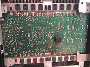
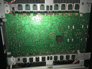
Excellent soldering & board clean up.Maybe I am missing something obvious?
 This probably isn't the issue but, why leave all that flux cheese around the big heat sink mounted trannies?
4 of 6 of the relay contacts are stashed under the black cushion. Did ya yank the cushion & reflow all contact solder points?
Last edited:
FriedChicken
Active Member
Yes. I replaced this relay after it failed and double checked the reflow.Excellent soldering & board clean up.
4 of 6 of the relay contacts are stashed under the black cushion. Did ya yank the cushion & reflow all contact solder points?
A lot of the flux is original from Yamaha lol
Sparkplug
Super Member
It gets rid of the noise generated by the zener diode which in turn is used to keep the current through the dual FETs constant. It’s common practice to use a 100 μF cap around zener diodes.What role does C100 play in the circuit?
The only other thought I had was double checking the poly caps under the TO3P trannies on the left channel. Just give them a wiggle and see if a lead came loose. I've had those poly's come loose while reflowing the outputs & APS trannies cuz the leads are stashed/shared under the tranny leads.
Anything beyond today's chat is beyond me & will leave ya to the more learned techs. Good luck Mr. Chicken.
Anything beyond today's chat is beyond me & will leave ya to the more learned techs. Good luck Mr. Chicken.
FriedChicken
Active Member
I now have more questions than answers. The dual FETs? As in all the output stages?It gets rid of the noise generated by the zener diode which in turn is used to keep the current through the dual FETs constant. It’s common practice to use a 100 μF cap around zener diodes.
Thank you; I don't understand what you mean by TO3P and APS transistors? I think I already tried reflowing everything I had touched.The only other thought I had was double checking the poly caps under the TO3P trannies on the left channel. Just give them a wiggle and see if a lead came loose. I've had those poly's come loose while reflowing the outputs & APS trannies cuz the leads are stashed/shared under the tranny leads.
Anything beyond today's chat is beyond me & will leave ya to the more learned techs. Good luck Mr. Chicken.
One thought I do have: I think I used RTV as a glue underneath some of the capacitors. Perhaps that glue is conductive??
I hope someone can give a well-rounded and complete explanation of the workings of this amplifier. It's going in that direction, and I'm all about learning rather than "just try this". It's been almost two decades since I've done in-depth circuit work/analysis/design.
I kinda like smell of old flux in the morning honestly...A lot of the flux is original from Yamaha lol