

-
Feeling lucky? Check out the AK 24th Anniversary Giveaway thread and join in the fun!
You are using an out of date browser. It may not display this or other websites correctly.
You should upgrade or use an alternative browser.
You should upgrade or use an alternative browser.
JbL L100T to L100T3 Crossover Conversion Cheat Sheet
- Thread starter GordonW
- Start date

Register to hide this ad
Haven't heard them back-to-back. My memory of the T3 is a bit dated, too.
From the diagram, it looks like they attenuated the tweeter a tad, and toned down the response a bit between the drivers (less chance of peaking at the crossover points). My "trained eye" would indicate probably perceived "smoother" response.
Regards,
Gordon.
From the diagram, it looks like they attenuated the tweeter a tad, and toned down the response a bit between the drivers (less chance of peaking at the crossover points). My "trained eye" would indicate probably perceived "smoother" response.
Regards,
Gordon.
Great work Gordon. Any chance of an L80T to L80T3 cheat sheet as well?
Indynryder
Active Member
Great job Gordon. Now lets add this element to the checklist when I get to this project, of many other speaker projects in waiting. I just wish I had more time.
avguytx
Lunatic Member
Thanks for this, Gordon. I'm going to get these parts ordered for my L100T's and do this modification. I'm going to go ahead and replace the other resistors and caps for the sake of doing it while I'm in there. I know resistors like these seldom fail (unless over driven and heated up) but, for the minimal cost, it's worth it to know they're new.
Now when you said, "arguably better", do you feel the T3 was an upgrade over the T crossover?
Now when you said, "arguably better", do you feel the T3 was an upgrade over the T crossover?
4343
Super Member
Gordon,
Have you had the inclination to measure the DCR of the "T" or "T3" inductors? I am currently researching parts for the upgrade. Thanks.
Rule of thumb with inductors in series with the woofer is lower DCR will result in the amp having tighter control of the woofer motion.
I used this Erse 16ga 3.3mH I core because it has the lowest DCR*:
http://www.parts-express.com/pe/showdetl.cfm?partnumber=266-914
Had to unwind a few turns to get it to 3.2mH. Bass is solid, but did not have much time on the stock setup as comparison, (so maybe better, maybe not, YMMV).
There is a pic of the inductor installed here:
http://www.audioheritage.org/vbulle...00T-quot-s-!!!&p=340694&viewfull=1#post340694
For the other inductors, I added enough turns of the same diameter wire to bring them up to the new values. This gets the DCR as close as possible to the original by only adding a few feet of wire to the original DCR...
* The 14ga 3.3 mH Jantzen Toroidal
(http://www.parts-express.com/pe/showdetl.cfm?partnumber=255-812)
_may_ have a lower DCR, but Toroidals are a lot harder to unwind. Either way you need an inductance meter to get it right:
http://www.parts-express.com/pe/showdetl.cfm?partnumber=390-570
Last edited:
Great work Gordon. Any chance of an L80T to L80T3 cheat sheet as well?
You can compare the differences in these links, and see the differences in crossover values.
For the record, I tried the L80t3 crossovers in my L80t's, and took them back out and sold them as I actually preferred the original crossover.
http://www.jbl.com/resources/Brands...edDocuments/en-US/technicalsheet//L80T ts.pdf
http://www.jbl.com/resources/Brands...dDocuments/en-US/technicalsheet//L80T3 ts.pdf
Last edited:
4343
Super Member
Ballpark...
For comparison, the 3.2mH I used measures about 0.25 ohms on the same Fluke meter. (Please note that readings below 1 ohm are notoriously inaccurate with most ohmmeters.)
Chasing down the original DCR for that particular inductor is pointless, as I outlined above. Less R between the amp and woofer is always better for motional control, and has almost zero effect on the woofer output level. That is why bi-amping almost always produces tighter bass, since the series inductor (with it's resistance) is eliminated from the circuit. I would hazard that the original designer was limited by the cost of the bigger inductor, but would have chosen a much lower DCR if allowed to. Case in point is the 4410A network.
Found here:
http://www.jblproservice.com/pdf/Network Schematics/4410A-RL Network.pdf
Notice that the designer has specified L1 DCR as LESS than 0.45 ohms, not an exact number. However L3 and L5 do have exact numbers, as they are critical in tuning that part of the circuit.
Measurement is about 0.6 ohms WITH about 5 turns added to make it 3.2mH, call it about 0.5 ohms on the original.Thanks for the reply. Do you still have the original 3.0 mH coil? If you could measure the DCR of the original, I would really appreciate it. Thanks.
For comparison, the 3.2mH I used measures about 0.25 ohms on the same Fluke meter. (Please note that readings below 1 ohm are notoriously inaccurate with most ohmmeters.)
Chasing down the original DCR for that particular inductor is pointless, as I outlined above. Less R between the amp and woofer is always better for motional control, and has almost zero effect on the woofer output level. That is why bi-amping almost always produces tighter bass, since the series inductor (with it's resistance) is eliminated from the circuit. I would hazard that the original designer was limited by the cost of the bigger inductor, but would have chosen a much lower DCR if allowed to. Case in point is the 4410A network.
Found here:
http://www.jblproservice.com/pdf/Network Schematics/4410A-RL Network.pdf
Notice that the designer has specified L1 DCR as LESS than 0.45 ohms, not an exact number. However L3 and L5 do have exact numbers, as they are critical in tuning that part of the circuit.
I've done 20 or 30 conversions to T3 on both versions of the crossover. I offered this over on the Lansing site for years. I even did a few L20T to 4406 conversions too (yes, they are very different).
I've seen a few "upgraded" crossovers on the 'bay which had Dayton caps but the original values. I'm sure there is value in that but the original problem of voicing remains, as do the coils which are typically undervalued.
The terminal post crossovers consistently had coils 10 percent undervalued, I wound them up to the T3 values and measured them to within 1% using an impedance meter. I measured them at the crossover frequency since iron cores can get a little non-linear at times.
The damping resistor on the T3 is 39 versus 41 ohms. I never change that since it doesn't make much of a difference. The drivers' impedance measured the same with either value.
What people like the most about the xovers I did was my attention to detail and assembly quality. Glue everything back on and make good connections.
I did one bi amp with level controls for the mid and high pass for a gentleman once. It was very challenging and I used a bridging terminal block so he could use one amp as well. Redoing the networks for L-pads took some testing, in the end it worked out.
I did a pair for 90 bucks and included return shipping on them. Most people thought it was a great deal considering how the midbass cleaned up and the highs were smoother. Every once in a while I get a request to do another pair. One guy in Vegas was so thrilled he mailed me a spare pair of crossovers to keep as a present; I modded them and they now grace my L100T Studio Monitor project.
Wayniac
Active Member
Measurement is about 0.6 ohms WITH about 5 turns added to make it 3.2mH, call it about 0.5 ohms on the original.
For comparison, the 3.2mH I used measures about 0.25 ohms on the same Fluke meter. (Please note that readings below 1 ohm are notoriously inaccurate with most ohmmeters.)
Chasing down the original DCR for that particular inductor is pointless, as I outlined above. Less R between the amp and woofer is always better for motional control, and has almost zero effect on the woofer output level. That is why bi-amping almost always produces tighter bass, since the series inductor (with it's resistance) is eliminated from the circuit. I would hazard that the original designer was limited by the cost of the bigger inductor, but would have chosen a much lower DCR if allowed to. Case in point is the 4410A network.
Found here:
http://www.jblproservice.com/pdf/Network Schematics/4410A-RL Network.pdf
Notice that the designer has specified L1 DCR as LESS than 0.45 ohms, not an exact number. However L3 and L5 do have exact numbers, as they are critical in tuning that part of the circuit.
Thanks for posting...I appreciate most of your comments, however researching the nominal specifications is not IMHO "pointless".
As reflected in my first post in this thread, I am interested in the DCR values for all of the coils in the crossover. Of particular interest is coil L2. I plan on replacing the coil with an upgraded part and will likely adjust the value of R3 based on the actual DCR of L2.
I like knowing the details, then making informed decisions based on the facts and my own personal experience. I was hoping the values would be readily available allowing me to keep my speakers in service while I researched and ordered the required replacements. Thanks Again.
SoundOfSound
Super Member
LRC calculations for midrange.
I have a pair of JBL L100T's that I originally bought back in 1988 when they first came out. I have been doing research on redoing the crossovers mainly because the old electrolytic caps are getting pretty old. First there was a challenge because some of the original values for the caps and resistors no longer exist in high quality audio parts, but that's no biggie. Now I'm finding information about re-voicing the speakers because of some kind of reported harshness in the speaker.
When I first bought the L100t's I had them set up with a Yamaha natural sound 100W/channel integrated amp. I also had them set up with the little metal stands that JBL sold that lifted them up about 4 inches off the ground. I also had them away from the wall about 6 to 10 inches along with everything else on that wall to act as a sort of sound plane for the back ports, The room also had carpet. In this configuration everything sounded great and there was no muddiness or floppiness from the bass or any harshness from the mids or the tweeters. In fact on many of the newer digital CD's the band sounded like they were in the room with you.
However since then I have been using a TEAC AV receiver and although the mids and high still sound good the bass is just not as tight and they don't kick you in the chest like they did with the Yamaha amp. So I'm thinking at least some of this reported muddiness from the woofers depends on how the speakers are set up and also how good the amp is being used to push them. Not to mention the electrolytic caps are getting pretty old too.
Now I'm trying to decide to keep them totally original or go nuts and do the super deluxe rebuild. In researching the differences between the T v.s. T3 crossovers I was doing some LRC calculations for the midrange and found out something pretty interesting. The reported crossover points on the literature state 800hz and 4500hz, So (4500 - 800) => (3700/2) => 1850. So 1850 Hz should be about the middle of the midrange band.
I cannot find a direct 17uF replacement for the mid but there are values above and below it that are close enough. Plus I'm strongly considering using
Mylar caps in the signal path because JBL used them so much during this period and I think they will help preserve the vintage JBL sound. They are also a step up from the electrolytic caps and will not dry up over time. So the next step is to narrow the choice of the three available values down to one.
So here is the interesting part assuming all parts are spot on, even though we know they are not. Plugging the values of the series LRC network, from the midrange, into the LRC resonace formula to find Fo we get.
(T3 Option) Fo using (.6mH and 15uF) = about 1680 Hz
(Modified T1 option) Fo using (.5mH and 18uF) = about 1680 Hz
So keeping the .5mH coil but changing the cap to 18uF gives you the same Fo resonance for the circuit as the T3 change over.
(Modified T3 option) Fo using (.5mH and 15uF) = about 1840 Hz
So that is the funny part. It looks like just making the cap change to 15uF and leaving the coil the same will actually get the resonance closer to the middle of the band (1850 Hz) where it supposedly belongs.
Has anybody actually swept these crossovers, (with good electrolytics in them), or do any other more rigorous mathematical testing on something like Matlab to see where the corners actually are?
Last edited:
I've done 20 or 30 conversions to T3 on both versions of the crossover. I offered this over on the Lansing site for years. I even did a few L20T to 4406 conversions too (yes, they are very different).
I've seen a few "upgraded" crossovers on the 'bay which had Dayton caps but the original values. I'm sure there is value in that but the original problem of voicing remains, as do the coils which are typically undervalued.
The terminal post crossovers consistently had coils 10 percent undervalued, I wound them up to the T3 values and measured them to within 1% using an impedance meter. I measured them at the crossover frequency since iron cores can get a little non-linear at times.
The damping resistor on the T3 is 39 versus 41 ohms. I never change that since it doesn't make much of a difference. The drivers' impedance measured the same with either value.
What people like the most about the xovers I did was my attention to detail and assembly quality. Glue everything back on and make good connections.
I did one bi amp with level controls for the mid and high pass for a gentleman once. It was very challenging and I used a bridging terminal block so he could use one amp as well. Redoing the networks for L-pads took some testing, in the end it worked out.
I did a pair for 90 bucks and included return shipping on them. Most people thought it was a great deal considering how the midbass cleaned up and the highs were smoother. Every once in a while I get a request to do another pair. One guy in Vegas was so thrilled he mailed me a spare pair of crossovers to keep as a present; I modded them and they now grace my L100T Studio Monitor project.
Duaneage may not post alot here on Ak, but he sure knows how to redo those crossovers. Old thread, I know, but thanks again, Duaneage! Still loving my JBL L100T (3) speakers. Well worth the money to make a good speaker great. :thmbsp:
salvador.gol
Member
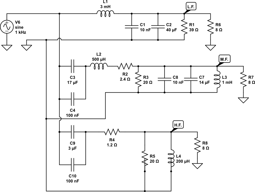
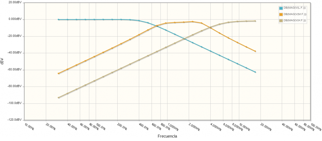
Long time ago since my last post... Since then I have been learning. I´ve got a pair of jbl l100t for $160 bucks in a flea market in mexico. I read Duaneage post for winding more turns on mids and woofer coils and have been playing with my soldering iron  . I have modified my l100t and they have a very nice sound now. The excercise i recomend you is listening them using a good eq before attempting modifications: study the frecuency ranges having the problem you want to work on. Listen many material such as diferent cd and vinyls so you can differentiate any possible recording or mastering deficiencies and not overcorrect them, also look for beefy amps that can move them easily. For reference I use a onyo integra A8087 or a sae2200. You can simulate free online crossover responses using circuitlab. Here I post the original crossover response from NL100t and what i think it works best for me and its response also.
1. Coupled in parallel 3.3uF (100V not poralized caps 10%tolerance) to 40uF woofer caps.
2. 32 turns more to mids coil. insulated 20awg copper wire. I dont know how this would be in mH It should be something near 700mH or 650mh?. If anybody do it, please comment the value. This should flatten the mid response.
3. Changed mids resistance 2.4 to 4 ohm to attenuate flattened mids.
I attach.
Hope this helps anybody :yes:


. I have modified my l100t and they have a very nice sound now. The excercise i recomend you is listening them using a good eq before attempting modifications: study the frecuency ranges having the problem you want to work on. Listen many material such as diferent cd and vinyls so you can differentiate any possible recording or mastering deficiencies and not overcorrect them, also look for beefy amps that can move them easily. For reference I use a onyo integra A8087 or a sae2200. You can simulate free online crossover responses using circuitlab. Here I post the original crossover response from NL100t and what i think it works best for me and its response also.1. Coupled in parallel 3.3uF (100V not poralized caps 10%tolerance) to 40uF woofer caps.
2. 32 turns more to mids coil. insulated 20awg copper wire. I dont know how this would be in mH It should be something near 700mH or 650mh?. If anybody do it, please comment the value. This should flatten the mid response.
3. Changed mids resistance 2.4 to 4 ohm to attenuate flattened mids.
I attach.
Hope this helps anybody :yes:


salvador.gol
Member
I forgot to mention. This upgrade costed only $10 dollar and believe me it is worth every penny ")