5F2A Tweed Princeton - To lower, or not to lower, B+ Voltages

Dig22

Active Member
Hi,
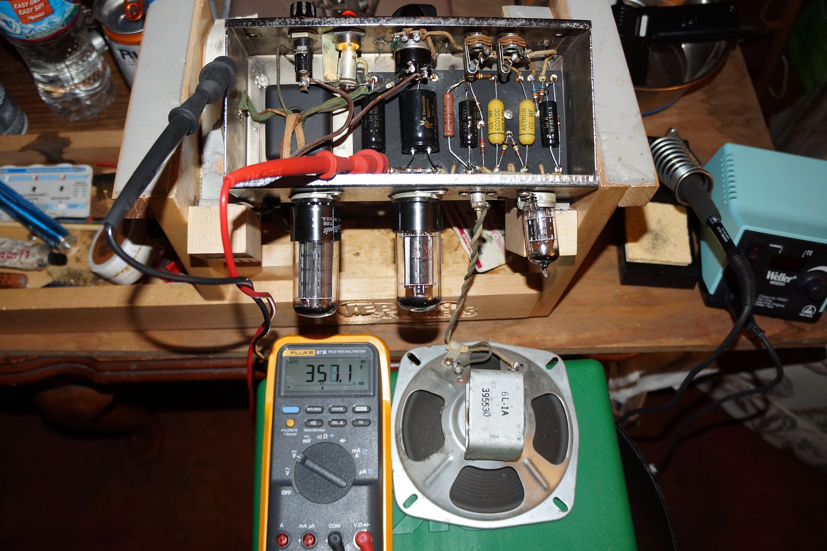
I've completed another 5F2A. I used the Weber layout. It runs quiet. Sounds good and will sound better with a better speaker.

My question is on the B+ voltages. My house current is 121V. Pending the tube, (I've tried a couple) Pin 8 of the 6V6 reads
20 - 21.8V. The 16@450 caps are reading 388-390V. The 8&450 are reading 346V & 303V.

My understanding, which may or may not me correct is that those voltages are high and might be pushing the 6V6 to an early grave. I'd like to hear what ya'll think. Should I lower the B+ voltage -- can someone explain a way to do that? Or should I not worry?

Thanks in advance for your help.Weber 5F2A layout.jpg
 

Attachments

  • Weber 5f2a_schem.jpg
    Weber 5f2a_schem.jpg
    77.1 KB · Views: 89
  • fender_princeton_5f2_schematic_volts.gif
    fender_princeton_5f2_schematic_volts.gif
    50 KB · Views: 15
Register to hide this ad
Hi, without knowing your plate voltage, I can't know exactly what the output tube is dissipating, but roughly 44mA across your 470 ohm resistor
should be no problem if your plate V in 310 or under. Maybe Mr Boochie will concur, but I wouldn't worry...

As a side note, you could look into running your vintage style amps through a voltage buck. They can be made fairly easy and your tube filaments
would be a bit happier too running at 117 or so... I use one or a variac on all my guitar amps. My 2 cents...
 
Pending the tube, (I've tried a couple) Pin 8 of the 6V6 reads 20 - 21.8V. The 16@450 caps are reading 388-390V.
Hi! First off, does the 6V6GT show signs of red plating, or early volume onset of overdrive distortion? Is it running much hotter than other output tubes you are used to?

As miles2go asked, measure the VDC at pin #3 (anode plate), with the black lead to the chassis. I think 390 VDC is not the correct value. If it is that high, you may want to replace that Weber solid-state WY3GT with a tube 5Y3GT. The plate voltage should be closer to 340-360 VDC.

Let's say the plate voltage is 390 VDC and the cathode voltage across the 470-ohm resistor is 20 VDC.

Current draw across the resistor is (voltage) divided by (resistance). 20/470 = 0.042 amps = 42 mA.

Idle wattage = (voltage) times (current). 390 X 0.042 = 16.59 watts. That number is too high for a typical 6V6GT (max dissipation around 12-14 watts for Class "A").

Lowering the plate voltage will also reduce the voltage across the cathode resistor (the tube draws less current at a lower plate voltage).

So, say with a 5Y3GT tube, you get 340 plate volts and 17 volts across the cathode resistor. Now, the current draw is 36 mA, and the dissipated power is 12.3 watts, which is 90% of the maximum dissipation of a healthy 6V6GT, running in Class "A" mode.

BTW. If you do decide to try a 5Y3GT tube, use an NOS US-made one. They are relatively cheap and WAY better than any modern-made ones.

3f270bc8-e532-4d99-bbaf-39b61c20ca60.jpg

Plate voltage of a newly recapped Champ (similar cathode-bias 6V6GT as yours).

Good luck! Keep us informed! :thumbsup:
 
Last edited:
Whats the heater voltage? Thats usually my guide. if its more than 5% high (over 6.6v) then I'll mess with the primary side to knock it all down at once.

If the heater is good, then I agree on the tube rectifier. Should knock it down 40v or so if its silicon now.
 
You could use the 5v winding as a bucker I guess. I would connect the 5v winding to the rectifier socket and use a 5Y3GT rectifier tube first. I would imagine most folks use a tube rectifier in these amps anyway.
 
You could use the 5v winding as a bucker I guess. I would connect the 5v winding to the rectifier socket and use a 5Y3GT rectifier tube first. I would imagine most folks use a tube rectifier in these amps anyway.
index.php


The B+ 390 VDC voltage of the Weber amp must be based on the solid-state WY3GT rectifier. It is a direct plug-in to the stock 5Y3GT socket. I have not seen a standard 5Y3GT amp supply B+ at 390 VDC — they are usually around 350-360 VDC. Of course, using a standard power transformer for a 6V6GT single-ended amp.

So, if this is the case, all he needs is to sub a 5Y3GT tube. It's worth a try. The 5Y3GT is prolly going to soften the tone. Small single-ended amps with solid-state rectification can sound sterile and compressed.

If the B+ is still too high, the PT must have PIV greater than the OEM tweed Champ or single-ended Princeton transformers.


index.php

Then, you could:

1.) Drop the B+ by adding a resistor between C2 and C9 (if this is a Weber Princeton clone amp).

2.) You can go to a larger cathode resistor (R8). Maybe try 600-ohms. I'd use a 5-watt resistor. :idea:

3.) Drop the resistance of the grid-to-ground resistor (R9) on the 6V6GT. From 220k-ohms to say 100k-ohms. I've found that you need to make significant changes to the G2G resistor to affect the idle bias.

4.) Run a bucking transformer.


Bucking transformer - Robinette.jpg
 
Last edited:
You could use the 5v winding as a bucker I guess. I would connect the 5v winding to the rectifier socket and use a 5Y3GT rectifier tube first. I would imagine most folks use a tube rectifier in these amps anyway.
You are correct. If this is the Weber Princeton clone amp kit, he will need to wire the 5VAC lines into the rectifier's socket, to use the 5Y3GT.

Thanks!
 
You are correct. If this is the Weber Princeton clone amp kit, he will need to wire the 5VAC lines into the rectifier's socket, to use the 5Y3GT.

Thanks!
I used a Weber power trany in a 6L6 SE head amp I built. The HV was a little high due to using a couple diodes for SS rectification. I wanted this amp to have a nice clean sound even at a high volume, so I didn't use a tube rectifier.
It worked. You had to crank the volume up really high with the controls on the Guitar cranked up as well to get it break up a little. It wasn't one of my sons favorites it turned out. I thought he might like to have at leased one amp like that, but he didn't. It wound up in a local studio. The local blues players like it though! :biggrin:
 
Hi! First off, does the 6V6GT show signs of red plating, or early volume onset of overdrive distortion? Is it running much hotter than other output tubes you are used to?

As miles2go asked, measure the VDC at pin #3 (anode plate), with the black lead to the chassis. I think 390 VDC is not the correct value. If it is that high, you may want to replace that Weber solid-state WY3GT with a tube 5Y3GT. The plate voltage should be closer to 340-360 VDC.

Let's say the plate voltage is 390 VDC and the cathode voltage across the 470-ohm resistor is 20 VDC.

Current draw across the resistor is (voltage) divided by (resistance). 20/470 = 0.042 amps = 42 mA.

Idle wattage = (voltage) times (current). 390 X 0.042 = 16.59 watts. That number is too high for a typical 6V6GT (max dissipation around 12-14 watts for Class "A").

Lowering the plate voltage will also reduce the voltage across the cathode resistor (the tube draws less current at a lower plate voltage).

So, say with a 5Y3GT tube, you get 340 plate volts and 17 volts across the cathode resistor. Now, the current draw is 36 mA, and the dissipated power is 12.3 watts, which is 90% of the maximum dissipation of a healthy 6V6GT, running in Class "A" mode.

BTW. If you do decide to try a 5Y3GT tube, use an NOS US-made one. They are relatively cheap and WAY better than any modern-made ones.

3f270bc8-e532-4d99-bbaf-39b61c20ca60.jpg

Plate voltage of a newly recapped Champ (similar cathode-bias 6V6GT as yours).

Good luck! Keep us informed! :thumbsup:
Thanks for your reply.
Let me clarify that I didn't build a Weber kit. No Weber parts in this build. I just used their layout and schematic because I've done so in the past.
The PT is Mojo Classic Truetone I pulled from an older unit. And the OT is a new Heyboer. I use a 5Y3 not solid state rectifier.

That said, the measurements are:
@ 121 VAC the first B+ is 388. 6V6 pin 3 is 376. Pin 8 is 21.5v
@117 VAC the first B+ is 376. 6V6 pin 3 is 365. Pin 8 is 20.8v
@110 VAC the first B+ is 356. 6V6 pin 3 is 345. Pin 8 is 19.5v

@121 VAC the Heaters measure 6.8

Let me know what other info you need and thanks again.
 
Whats the heater voltage? Thats usually my guide. if its more than 5% high (over 6.6v) then I'll mess with the primary side to knock it all down at once.

If the heater is good, then I agree on the tube rectifier. Should knock it down 40v or so if its silicon now.
thanks for replying.

@117V the heater voltage is 6.6
@121V the heater voltage is 6.8
 
Thanks for your reply.
Let me clarify that I didn't build a Weber kit. No Weber parts in this build. I just used their layout and schematic because I've done so in the past.
The PT is Mojo Classic Truetone I pulled from an older unit. And the OT is a new Heyboer. I use a 5Y3 not solid state rectifier.

That said, the measurements are:
@ 121 VAC the first B+ is 388. 6V6 pin 3 is 376. Pin 8 is 21.5v
@117 VAC the first B+ is 376. 6V6 pin 3 is 365. Pin 8 is 20.8v
@110 VAC the first B+ is 356. 6V6 pin 3 is 345. Pin 8 is 19.5v

@121 VAC the Heaters measure 6.8

Let me know what other info you need and thanks again.
I forgot to mention, there is no red plating.
 
Yeah I'd knock down the primary if you can. Thermistor might do it, or a bucking transformer. If you have an extra heater winding that could be used for the purpose.

6.8v is 8% over so if you can get the primary down enough to get that at 6.3, the others will drop by 8% too.
Is it an issue with the PT?
 
Not an issue exactly. Sounds like it was wound for 110v rather than 120v. Or its a much higher capacity transformer than you are making use of and its just not loaded down enough.

Either way if you knock back the input voltage the other voltages will come down with it. If its currently at 390v B+, 8% down is 360v which is right in line with what @Mr Boochie says is typical. He's worked on these, I haven't. I've just dealt with old stuff wound for lower mains voltages and these sort of problems come up.
 
Is it an issue with the PT?
Yeah I'd knock down the primary if you can. Thermistor might do it, or a bucking transformer. If you have an extra heater winding that could be used for the purpose.

6.8v is 8% over so if you can get the primary down enough to get that at 6.3, the others will drop by 8% too.

Not an issue exactly. Sounds like it was wound for 110v rather than 120v. Or its a much higher capacity transformer than you are making use of and its just not loaded down enough.

Either way if you knock back the input voltage the other voltages will come down with it. If its currently at 390v B+, 8% down is 360v which is right in line with what @Mr Boochie says is typical. He's worked on these, I haven't. I've just dealt with old stuff wound for lower mains voltages and these sort of problems come up.
The transformer was built for this circuit. It's 10 or 15 years old.
 
index.php


The B+ 390 VDC voltage of the Weber amp must be based on the solid-state WY3GT rectifier. It is a direct plug-in to the stock 5Y3GT socket. I have not seen a standard 5Y3GT amp supply B+ at 390 VDC — they are usually around 350-360 VDC. Of course, using a standard power transformer for a 6V6GT single-ended amp.

So, if this is the case, all he needs is to sub a 5Y3GT tube. It's worth a try. The 5Y3GT is prolly going to soften the tone. Small single-ended amps with solid-state rectification can sound sterile and compressed.

If the B+ is still too high, the PT must have PIV greater than the OEM tweed Champ or single-ended Princeton transformers.


index.php

Then, you could:

1.) Drop the B+ by adding a resistor between C2 and C9 (if this is a Weber Princeton clone amp).

2.) You can go to a larger cathode resistor (R8). Maybe try 600-ohms. I'd use a 5-watt resistor. :idea:

3.) Drop the resistance of the grid-to-ground resistor (R9) on the 6V6GT. From 220k-ohms to say 100k-ohms. I've found that you need to make significant changes to the G2G resistor to affect the idle bias.

4.) Run a bucking transformer.


View attachment 3650179
What size resitor would you add between C2 & C9? and are you recommending all those steps together, or pick and choose?
 
Not an issue exactly. Sounds like it was wound for 110v rather than 120v. Or its a much higher capacity transformer than you are making use of and its just not loaded down enough.

Either way if you knock back the input voltage the other voltages will come down with it. If its currently at 390v B+, 8% down is 360v which is right in line with what @Mr Boochie says is typical. He's worked on these, I haven't. I've just dealt with old stuff wound for lower mains voltages and these sort of problems come up.
Yes. You can use the 12% voltage-reduction outlet on Robinette's bucking transformer.

index.php


___________________________________


"What size resistor would you add between C2 & C9? And are you recommending all those steps together, or pick and choose?"

From the diagram, a 10k-ohm resistor drops the voltage from 388 VDC to 346 VDC. "The 16@450 caps are reading 388-390V. The 8&450 are reading 346V & 303V."
That's a 42-volt drop. So, a 5k-ohm resistor between C2 and C9 should drop the voltage about 21 volts. Theoretically, dropping B+ from 388 to 367.

I'd use a 2-watt or larger metal-oxide resistor.
Thanks. That's easy. But how does it affect the sound?
 
Back
Top Bottom